
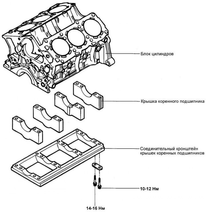
Fig. 2.221. Cylinder block components
Disassembly
Remove the cylinder head, timing belt, front cover, automatic transmission drive plate, automatic transmission mounting plate, oil pan, pistons and crankshaft.
Details of disassembly are provided below in the relevant sections
Examination
Check the cylinder block for chips, corrosion, scale deposits and rust. Also check for cracks and other damage. Replace the cylinder block if significant defects are found.
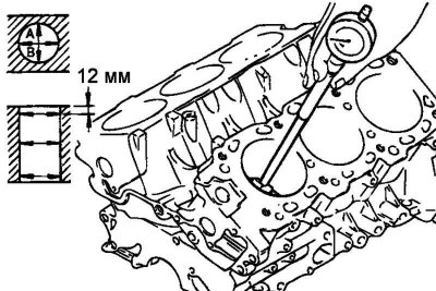
Fig. 2.222. Measuring the diameter of cylinders using a bore gauge
Measure the diameter of the cylinders using a bore gauge in three zones along the height in directions "A" and "B" (Fig. 2.222).
Level 1: Piston TDC.
Level 2: Mid-move.
Level 3: Piston BDC.
If the cylinder out-of-roundness (ovality) or taper is greater than the maximum permissible value, or there are scratches or signs of seizure (scuffing) on the cylinder mirror, then the cylinders of the block should be bored to the appropriate repair size and honed. After repairing the cylinder block, install pistons and piston rings of the appropriate repair size.
Nominal value: cylinder diameter – 86.7 mm.
The maximum permissible value of cylinder taper and ovality: no more than 0.02 mm.
If there is an annular wear groove in the area where the first compression ring stops at TDC, remove the groove crest using a reamer or scraper.
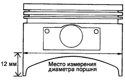
Fig. 2.223. Location of piston diameter measurement
When repairing (boring and honing) cylinders to the repair size, calculate the bore diameter of the cylinder so that the repair results in a nominal clearance between the piston and the cylinder. All pistons installed must be of the same repair size. Piston diameter measurements are taken at a distance of 12 mm from the skirt edge in a plane perpendicular to the piston pin axis (Fig. 2.223).
Clearance between piston and cylinder: 0.01–0.03 mm.
Make sure there is no damage or cracks in the cylinder walls.
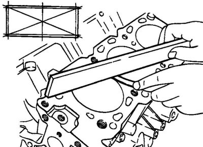
Fig. 2.224. Measuring the plane of a block for warping
Using a straightedge and a flat feeler gauge, check the warping of the block mating surface under the head. Before checking, remove any old gasket residue and foreign particles from the mating surface (Fig. 2.224).
Nominal value: flatness - 0.03 mm or less.
Maximum permissible value: non-flatness – no more than 0.05 mm.
Attention! When restoring the surface by mechanical processing, the amount of metal removed should not exceed 0.2 mm
Cylinder boring
When repairing, the maximum cylinder diameter is taken into account.
Note: The piston repair size mark is stamped on the fire bottom.
[The original source of the article is the website: www.HyundaiBook.ru]
Note: Measure the piston diameter to be installed in this cylinder.
Based on the measured piston outside diameter, calculate the cylinder bore diameter.
Cylinder bore diameter = piston outer diameter + clearance between piston and cylinder (0.01–0.03 mm) – honing allowance (0.01 mm).
Bore all cylinders to the calculated diameter.
Note: When boring, to prevent thermal deformations of the cylinder walls, bore in the order of engine operation.
Honing of the cylinder walls is carried out until the specified piston-cylinder clearance is achieved.
After honing, recheck the clearance. Nominal value: 0.01–0.03 mm.
Note: Install only pistons of the same oversize into the engine
Assembly
Install the parts listed below into the block.
- 1. Crankshaft.
- 2. Automatic transmission drive plate.
- 3. Pistons.
- 4. Cylinder heads.
- 5. Timing belt.
- 6. Front cover.