
Contents: Disassembly ⇓ Examination ⇓ Front camshaft oil seal ⇓ Hydraulic pusher ⇓ Checking the timing chain ⇓ Installation ⇓ Valve Cover Bolt Tightening Procedure ⇓
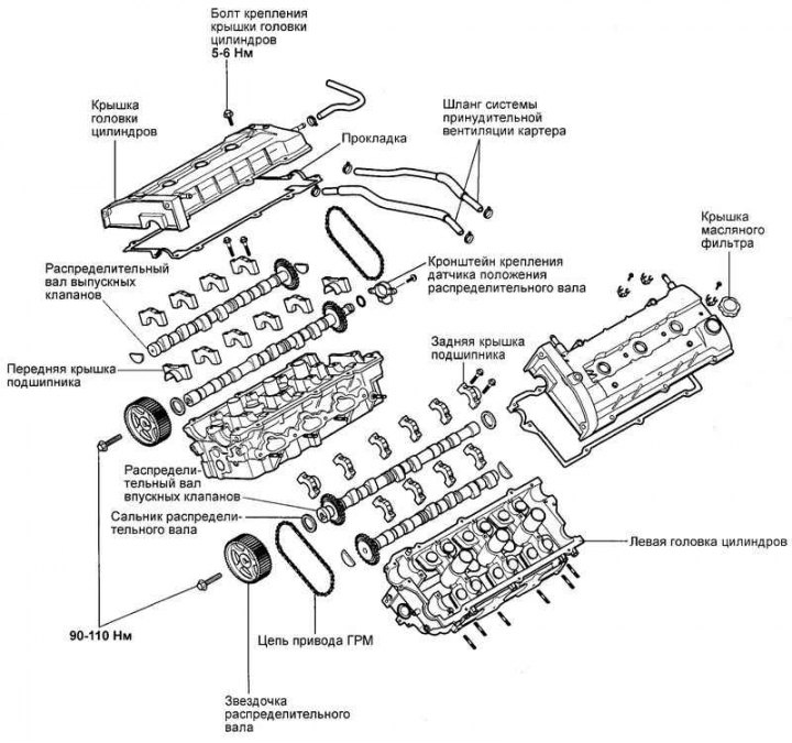
Fig. 2.238. Components of camshafts
Disassembly
Drain the coolant. Remove the engine cover and intake manifold.
Disconnect the positive crankcase ventilation hose and disconnect the engine wiring harness connector.
Remove the accessory drive belt. Remove the power steering pump pulley, air conditioning compressor pulley, crankshaft pulley, tensioner pulley and idler pulley.
Remove the timing belt cover.
Remove the automatic timing belt tensioner.
Remove the belt from the camshaft sprockets.
Remove the high voltage wires.
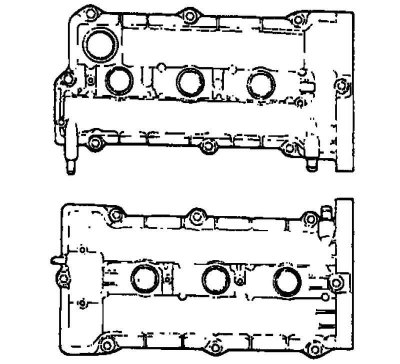
Fig. 2.239. Valve covers
Remove the valve covers (Fig. 2.239).
Remove the camshaft sprockets (under the timing belt).
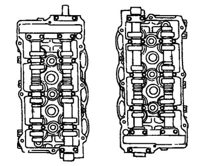
Fig. 2.240. Camshafts
Loosen the camshaft bearing cap mounting bolts (Fig. 2.240).
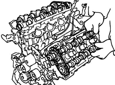
Fig. 2.241. Removing the camshafts
Remove the bearing caps and camshafts (Fig. 2.241).
Examination
Check the camshaft journals for wear. If the journals are significantly worn, replace the camshaft.
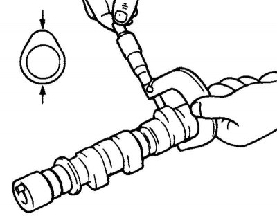
Fig. 2.242. Measuring the height of the camshaft cams
Check the camshaft cam tops for damage. If the cams are damaged or their wear exceeds the permissible value, replace the camshaft (Fig. 2.242).
Height of camshaft lobes.
Nominal value:
- inlet - 43.95-44.15 mm;
- outlet - 43.95-44.15 mm.
Maximum permissible value:
- inlet and outlet - 43.45 mm.
Check the condition of the camshaft back. If there is damage or wear, replace the camshaft.
Check the condition of the camshaft bearings in the cylinder head. If there is significant damage or wear, replace the cylinder head assembly. Measure the axial clearance of the camshaft.
Axial clearance: 0.10–0.15 mm.
Front camshaft oil seal
Check the condition of the sealing lip of the oil seal. Replace the oil seal if necessary.
Check the condition of the camshaft journal for installing the seal. If there is a wear groove, replace the camshaft.
Hydraulic pusher
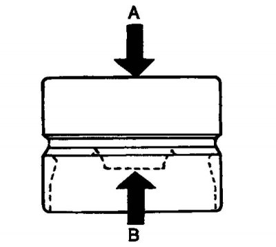
Fig. 2.243. Scheme of actions when filling the pusher with small
Fill the tappet with oil. Having created a stop on the surface "A" press with your hand on the projection "B" (Fig. 2.243). If there is movement, replace the tappet. Other typical malfunctions of the hydraulic compensator are listed in table 2.13.
Checking the timing chain
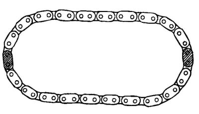
Fig. 2.244. Timing chain
Check the chain components (bushings and plates) for wear. Replace the chain if wear is excessive (Fig. 2.244).
(The original text is located on the portal: «hyundaibook»)
Installation
Install the hydraulic lifters into place.
Align the timing chain with the intake and exhaust camshaft sprockets.
Lubricate the camshaft bearing journals with engine oil, then install the camshaft in place.
Note: Before installation, check the pressing force of the intake camshaft sprocket. At room temperature, the force should be above 1000 kg.
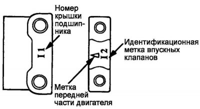
Fig. 2.245. Identification marks on bearing caps
Install the camshaft bearing caps. The identification marks on the bearing caps are intended to identify the installation location of the cap (inlet/outlet valve side) (Fig. 2.245).
I: Intake camshaft.
E: exhaust camshaft.
Tighten the camshaft bearing cap bolts to the specified torque in two or three steps.
Tightening torque of the camshaft bearing cover bolts: M10 – 14–16 N·m, M7 – 10–12 N·m.
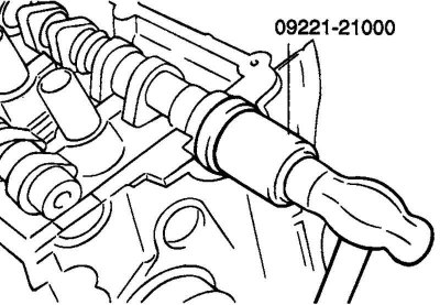
Fig. 2.246. Pressing in the camshaft oil seal
Using a special tool (mandrel for installing the camshaft seal: 09221-21000), press in the camshaft seal. Lubricate the sealing lip of the seal with engine oil (Fig. 2.246).
Place the oil seal on the camshaft from the timing belt sprocket side, then use a hammer to tap the mandrel until the oil seal is seated.
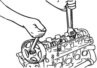
Fig. 2.247. Installing the camshaft sprocket
Install the camshaft sprockets and tighten the mounting bolts to the specified tightening torque (Fig. 2.247).
Tightening torque of the camshaft sprocket mounting bolts: 90–110 N·m.
Install the valve cover.
Tightening torque of valve cover mounting bolts: 5–6 N·m.
Valve Cover Bolt Tightening Procedure
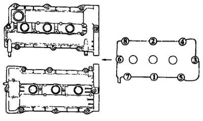
Fig. 2.248. Tightening order of valve cover bolts
Tighten the bolts in the sequence 1, 2, 3, 4, 5, 6, 7, 8 to half the tightening torque (Fig. 2.248).
Tighten all bolts to the specified torque.
Install the high voltage wires and center cover.
Install the timing belt and automatic tensioner.
Install the timing belt covers.
Install the power steering pump pulley, air conditioning compressor pulley, crankshaft pulley, tensioner pulley and idler pulley. Install the accessory drive belt.
Connect the positive crankcase ventilation hose and the engine wiring harness connector.
Install the intake manifold and engine cover.