Removal
1. Disconnect the crankcase ventilation hose.
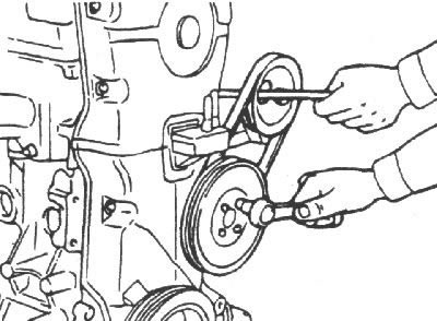
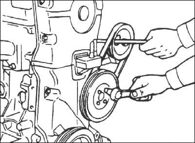
2. Remove the water pump pulley and crankshaft.
3. Remove the timing belt cover.
4. Move the timing belt tension roller away and temporarily secure it in this position.
5. Remove the timing belt from the camshaft pulley.
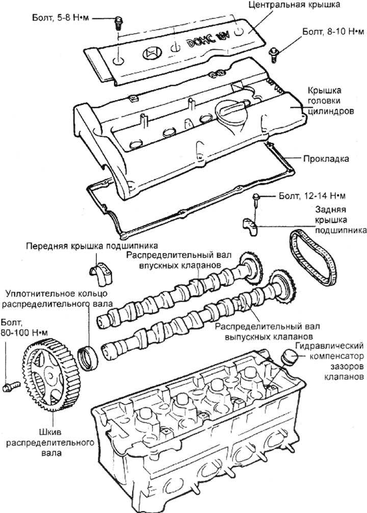
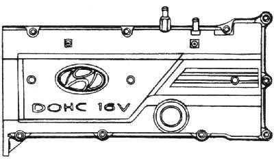
6. Remove the screws and remove the center cover.
7. Remove the ignition coil assembly.
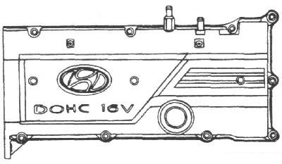
8. Remove the bolts and remove the cylinder head cover.
9. Remove the camshaft pulley.
10. Remove the camshaft bearing caps and drive chain.
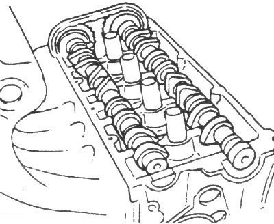
11. Remove the camshafts.
12. Remove the hydraulic valve clearance compensators.
Examination
Camshafts
1. Inspect the camshaft for uneven wear, cracks or damage.
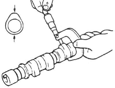
2. Measure the height of each camshaft lobe at two points.
- Nominal height of intake camshaft cams: 43.4484 mm
- Nominal height of exhaust camshaft cams: 43.8489 mm
- Minimum permissible height of intake camshaft cams: 42.9484 mm
- Minimum allowable height of exhaust camshaft: 43.3489 mm
3. Check the cam surfaces for uneven wear and damage.
4. Check each bearing for damage. If the bearing running surface is excessively damaged, replace the cylinder head or camshaft bearing cap.
Axial clearance of the camshaft: 0.1–0.2 mm
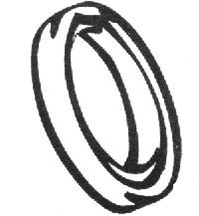
Front camshaft seal ring
1. Check the sealing lips for wear. If the sealing lips are worn or damaged, replace the sealing ring.
2. Check the surface of the camshaft that contacts the sealing ring. If this surface is unevenly worn, replace the camshaft.
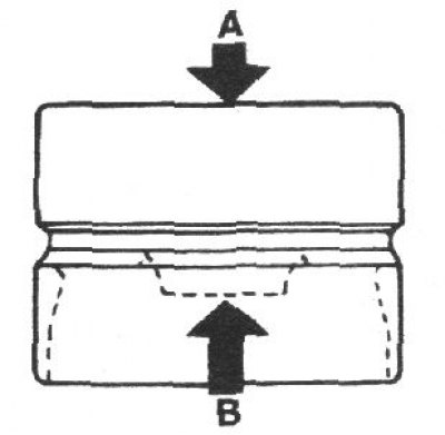
Hydraulic valve clearance compensators
Fill the hydraulic valve clearance compensator with engine oil, hold it vertically and squeeze it from both sides with your fingers.
The main faults of hydraulic valve clearance compensators, their causes and methods of elimination are given in the table.
| Malfunction | Possible reasons | Method of elimination |
| • Temporary noise when starting a cold engine | Normal phenomenon | The noise disappears after the engine oil warms up and reaches normal pressure |
| • Continuous noise after the engine has not been started for 48 hours | Oil leaked from the chambers of the hydraulic valve clearance compensators and air got into them | The noise will disappear after 15 minutes of engine operation, when the engine crankshaft reaches a speed of 2000–3000 min⁻¹⁻¹ Attention Do not increase engine speed above 3000 rpm⁻¹, as this can damage the hydraulic valve clearance compensators |
| • Continuous noise after engine start and cylinder head replacement | Not enough oil in the engine oil passages | |
| • Continuous noise after prolonged engine starting with the starter or by towing | Oil leaked from the chambers of the hydraulic valve clearance compensators and air got into them | |
| • Continuous noise after replacing hydraulic valve clearance compensators | ||
| • Continuous noise, at idle speed after driving at high speed | Engine oil level is too low or too high | Check the engine oil level |
| A large amount of air is dissolved in the oil after high speed rotation | Check the oil supply system | |
| Deterioration of motor oil properties | Check the quality of the oil. | |
| • The noise continues for more than 15 minutes | Low pressure in the lubrication system | Check the pressure in the lubrication system |
| Hydraulic valve clearance compensators are faulty | Remove the cylinder head and, by pressing on the hydraulic valve clearance compensators, check the amount of their compression Attention Beware of burns from hot hydraulic valve lifters |
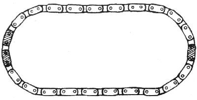
Chain
Check the chain bushings and plates for uneven wear, cracks or damage and replace if necessary.
Installation
1. Install hydraulic valve clearance compensators.
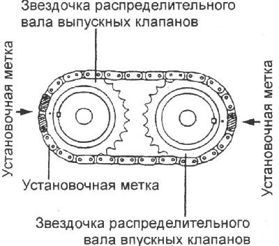
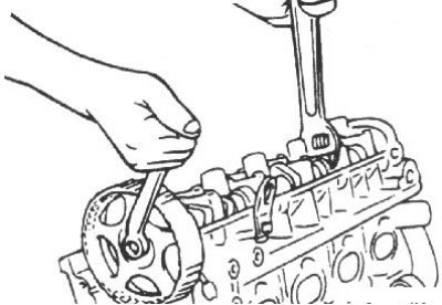
2. Install the chain on the camshaft sprockets, aligning the chain marks with the sprocket marks as shown in the figure.
3. Before installation, apply a thin layer of clean engine oil to all sliding surfaces of the camshafts. Install the camshafts.
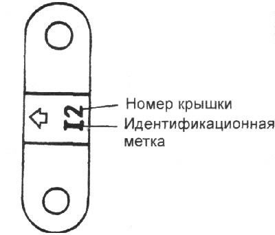
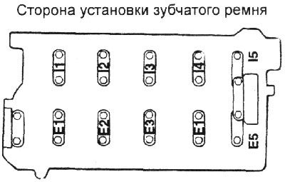
4. Install the camshaft bearing caps. Check the identification marks to identify the intake or exhaust camshafts.
- Intake valve camshaft: I
- Exhaust camshaft: E
5. Tighten the bearing cap bolts to the specified torque. Tightening torque: 12–14 N·m
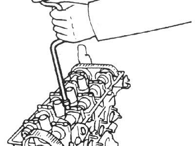
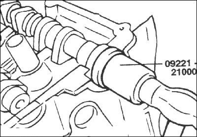
6. Lubricate the working edges and the outer surface of the sealing ring with engine oil and use special tool 09221–21000 to install the sealing ring onto the front of the camshaft.
Using a hammer blow on a special device, install the sealing ring until it stops in the socket.
7. Install the camshaft pulley and secure it with the bolt.
Tightening torque: 80–100 Nm
8. Align the camshaft timing mark and the crankshaft pulley timing mark with the pointers, with the piston of the 1st cylinder at TDC in the compression stroke.
9. Install the cylinder head cover and tighten the cover mounting bolts to the specified torque.
Tightening torque: 8–10 Nm
10. Install the high-tension wires, ignition coils and center cover.
11 Install the timing belt and tighten the timing belt tensioner.
12. Install the timing belt covers.
Tightening torque: 8–10 Nm
13. Install the water pump pulley and crankshaft.