
Contents: Disassembly ⇓ Checking the pushers ⇓ Checking the camshaft ⇓ Camshaft cam height ⇓ Assembly ⇓
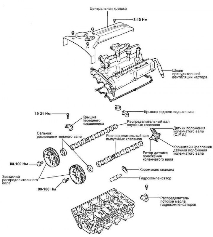
Fig. 2.43. Camshafts and tappets
Disassembly
Disconnect the battery.
Drain the coolant.
Disconnect the positive crankcase ventilation hose.
Remove the air filter.
Remove the timing belt cover.
Loosen the cylinder head cover mounting bolts, remove the cover and the crankshaft position sensor.
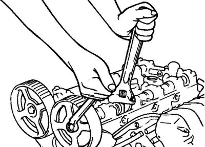
Fig. 2.44. Removing the camshaft sprockets
Remove the camshaft sprockets (Fig. 2.44).
Loosen the camshaft bearing cap mounting bolts. Remove the bearing caps, camshafts, tappets and clearance compensators.
Attention! Loosen the bearing cap mounting bolts in several steps to avoid deformation of the camshaft.
Checking the pushers
Check the smooth rotation of the tappet roller. If it rotates unevenly or if the gap is too large, replace the tappet.
Assess the condition of the roller surface. If there are chips or metal dragging, replace the pusher.
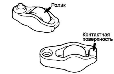
Fig. 2.45. Checking the contact surface of the pusher
Check the condition of the contact surface of the tappet (tip) with the valve. If the tip is worn, replace the tappet (Fig. 2.45).
Checking the camshaft
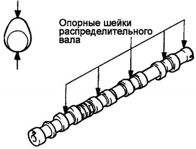
Fig. 2.46. Checking the camshaft bearing journals
Check the camshaft journals for wear. If the journals are significantly worn, replace the camshaft (Fig. 2.46).
Check the camshaft lobes for damage. If the lobes are damaged or worn beyond the specified limits, replace the camshaft.
Camshaft cam height
Nominal value:
Intake – 35.493 mm.
Graduation:
- (2.4L) Manual - 35.204 mm;
- (2.0L) Manual - 35.317 mm;
- Automatic transmission - 35.204 mm.
Maximum permissible value:
Intake – 34.993 mm.
Graduation:
- (2.4L) Manual - 34.704 mm;
- (2.0L) Manual - 34.817 mm;
- Automatic transmission - 34.704 mm.
Assembly
Place the camshafts in the bearing beds in the head. There is no need to install the tappets.
Note: Lubricate the journals and camshafts with engine oil.
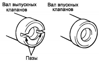
Fig. 2.47. Slot for installing the crankshaft position sensor
The exhaust camshaft has a slot at the rear end for installing the crankshaft position sensor (Fig. 2.47).

Fig. 2.48. Marks on the camshaft bearing caps
(The article is borrowed from the website HyundaiBook)
Install the camshaft bearing caps. Marks on the bearing caps indicate the installation locations (inlet/outlet valve side) (Fig. 2.48).
I: Intake camshaft.
E: exhaust camshaft.
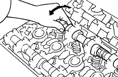
Fig. 2.49. Installing the pushers
Tighten the camshaft bearing cap mounting bolts to the specified torque. Check the shafts for smooth rotation. Remove the bearing caps and install the tappets (Fig. 2.49).
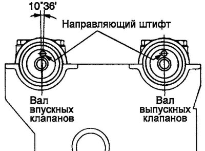
Fig. 2.50. Camshaft installation diagram
Install the camshafts so that the guide pins are positioned as shown in Figure 2.50.
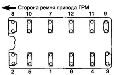
Fig. 2.51. Tightening order of camshaft bearing cap bolts
Tighten the camshaft bearing cap bolts to the specified torque in two or three steps and in the sequence shown in Figure 2.51.
Note: Make sure the valve rocker arm is properly installed on the hydraulic lifter and valve stem.
Note: Tightening torque of the camshaft bearing cover bolt: 19–21 N·m.
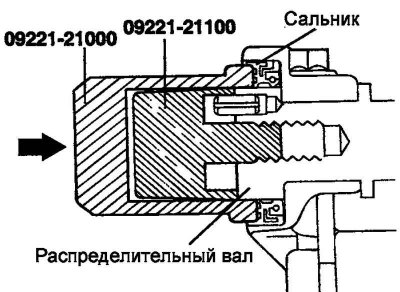
Fig. 2.52. Pressing in the camshaft seal using a special tool
Using a special tool (mandrel for installing the camshaft seal: 09221-21000, 09221-21100), press in the camshaft seal (Fig. 2.52).
Lubricate the sealing lip of the oil seal with engine oil. Place the oil seal on the camshaft from the timing belt sprocket side, then use a hammer to tap the mandrel until the oil seal is seated.
Install the camshaft sprockets and tighten the mounting bolts to the specified torque.
Tightening torque of the camshaft sprocket mounting bolt: 80–100 N·m.
Fig. 2.53. Installing the valve cover
Install the valve cover (Fig. 2.53).
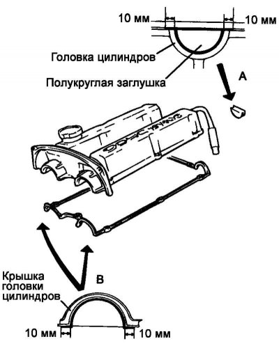
Fig. 2.54. Cylinder head cover and center cover fastening bolts: A – 13 EA (cylinder head cover); B – 4EA (central cover).
Tightening torque of cylinder head cover mounting bolts: 8–10 N·m, central cover mounting bolts: 4–5 N·m (Fig. 2.54).
Sealant used when installing the cylinder head cover:
- zone A - Three Bond No.10 or equivalent;
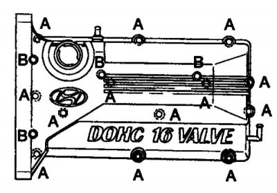
Fig. 2.55. Sealant application zones
- zone B - Three Bond No.1212D or equivalent (Fig. 2.55).
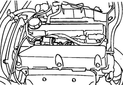
Fig. 2.56. High voltage wires
Install the spark plugs and ignition coils. Connect the high-tension wires and install the center cover (Fig. 2.56).
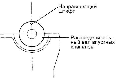
Fig. 2.57. Installing the intake camshaft sprocket guide pin
Install the intake camshaft sprocket guide pin as shown in Figure 2.57.
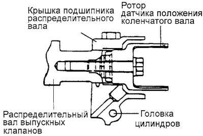
Fig. 2.58. Installing the cylinder and rotor support of the crankshaft position sensor
Install the cylinder and the crankshaft position sensor rotor support (Fig. 2.58).