
Contents: Removal ⇓ Checking the sprockets, timing belt…⇓ Checking the automatic tensioner ⇓ Checking the timing belt ⇓ Installation ⇓
The components of the timing belt are shown in Figure 2.14.
Removal
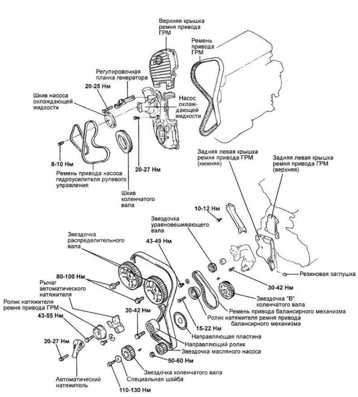
Fig. 2.14. Timing belt components
Remove the crankshaft and coolant pump pulleys and the pump drive belt (Fig. 2.14).
Attention! Turn the crankshaft clockwise until the timing marks on the crankshaft sprocket and the block are aligned, corresponding to the TMP of the piston of the 1st cylinder.
Attention! The timing marks of the camshaft sprockets must be aligned with the reference marks on the cylinder head (the sprocket guide pins are facing upwards).
Remove the timing belt cover.
Remove the automatic timing belt tensioner.
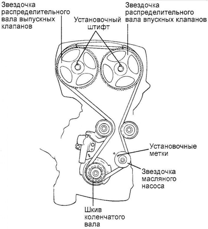
Fig. 2.15. Timing belt contour
Note: If the timing belt is reused, it is necessary to mark with chalk on the reverse (non-working) surface of the belt an arrow indicating the direction of rotation (or the location of the crankshaft pulley) so as not to confuse the direction of its rotation when installing the belt.
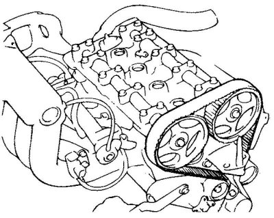
Fig. 2.16. Removing the timing belt
Remove the timing belt (Fig. 2.16).
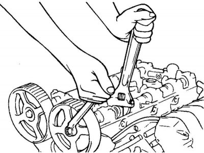
Fig. 2.17. Removing the camshaft sprockets
Remove the camshaft sprockets (Fig. 2.17).
Note: Be careful not to damage the cylinder head with the wrench when removing the camshaft sprocket.
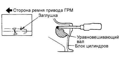
Fig. 2.18. Fixing the balance shaft
Before removing the oil pump sprocket, unscrew the plug on the left side of the block and insert an 8 mm screwdriver into the plug hole to secure the balance shaft. The screwdriver should go into the hole to a depth of more than 60 mm (Fig. 2.18).
Loosen the oil pump sprocket mounting nut and remove the sprocket.
Loosen the right balance shaft sprocket mounting bolt so that it can be turned by hand.
Remove the tensioner and balance shaft drive belt.
Caution: After removing the balance shaft belt, do not attempt to loosen the balance shaft sprocket bolt by holding the balance shaft sprocket with pliers or similar tool.
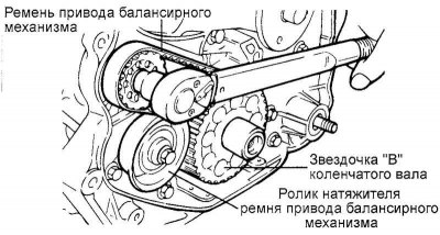
Fig. 2.19. Removing the sprocket "B" of the balance shaft drive
Remove the balance shaft drive sprocket "B" from the crankshaft (Fig. 2.19).
Checking the sprockets, timing belt tensioner roller and guide roller
Check the camshaft sprocket, crankshaft sprocket, timing belt tensioner pulley and idler pulley for excessive wear, cracks or damage. Replace if necessary.
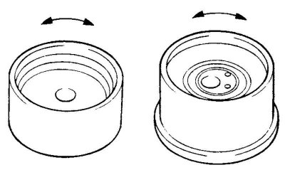
Fig. 2.20. Checking the timing belt tensioner roller
Check the ease and smoothness of rotation of the timing belt tensioner roller and guide roller and make sure there is no excessive play or extraneous noise when rotating. Replace parts if necessary (Fig. 2.20).
Replace the roller if you find signs of grease leaking from its bearing.
Checking the automatic tensioner
Check for fluid leaks from the tensioner. Replace the tensioner if necessary.
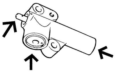
Fig. 2.21. Checking the condition of the tensioner pusher tip
Check the condition of the tensioner push rod tip. If damaged or worn, replace the tensioner (Fig. 2.21).
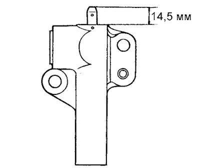
Fig. 2.22. Checking the protrusion of the pusher from the tensioner housing
Measure the protrusion of the push rod from the tensioner housing (Fig. 2.22).
If the protrusion is not equal to the nominal value, replace the tensioner.
Nominal size: 14.5 mm.
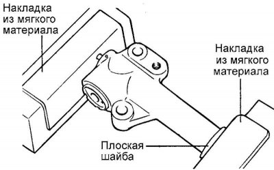
Fig. 2.23. Checking the force of movement of the pusher in the tensioner housing
Place the tensioner in a vice with soft metal jaws. Slowly insert the pusher into the housing. If the movement force is small, replace the tensioner. Check several times (Fig. 2.23).
Note: The tensioner in the vice must be installed evenly, without distortions. Be sure to use soft linings of the vice jaws.
Checking the timing belt
Check the belt for dirt or oil deposits. Replace if necessary.
Remove minor dirt from the belt with a dry cloth or cleaning paper.
Do not use solvents for these purposes.
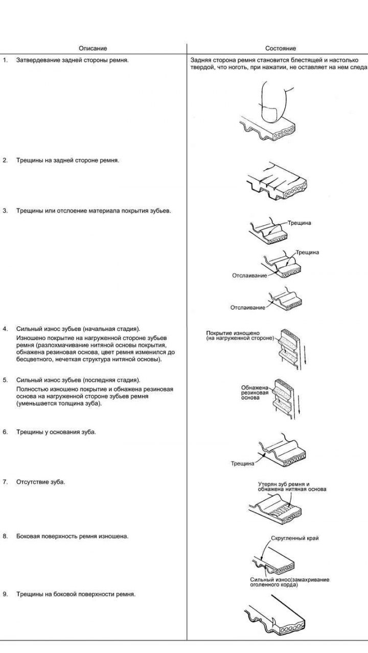
Fig. 2.24. Examples of damage and defects of the timing belt
When overhauling the engine or adjusting the belt tension, carefully inspect the belt. If any of the following defects are found, replace the belt with a new one (Fig. 2.24).
Installation
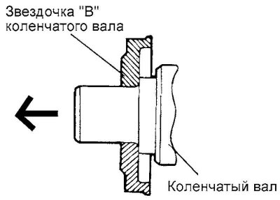
Fig. 2.25. Installing the balance shaft drive sprocket "B" on the crankshaft
Install the balance shaft drive sprocket "B" onto the crankshaft (Fig. 2.25).
Caution! Pay attention to the orientation of the sprocket flange. If the sprocket is installed incorrectly, the belt will break.
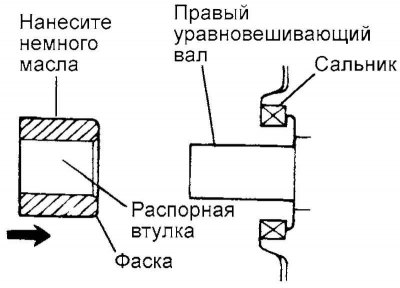
Fig. 2.26. Diagram of installation of spacer on the right balance shaft
Lubricate the spacer with engine oil and install it on the right balance shaft (Fig. 2.26).
Observe the installation orientation of the spacer.
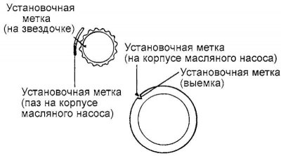
Fig. 2.27. Alignment of marks on balance shaft sprockets with reference marks
Install the drive sprocket on the right balance shaft and tighten the sprocket mounting bolt by hand. Align the marks on the balance shaft sprockets with the reference marks (Fig. 2.27).
Install the balance shaft drive belt without slack in the drive branch.
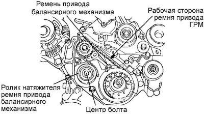
Fig. 2.28. Installing the balance shaft belt tensioner
Install the balance shaft belt tensioner so that its center is located to the left of the mounting bolt, and the roller flange is directed toward the crankshaft pulley (Fig. 2.28).
Align the timing mark on the right balance shaft with the reference mark.
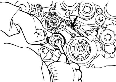
Fig. 2.29. Belt tension
Turn the tensioner to tighten the belt until the slack is removed. When tightening the tensioner mounting bolt, make sure that the shafts do not turn. If the shafts turn, the belt will be over-tensioned (Fig. 2.29).
Check the alignment of the installation marks with the reference marks.
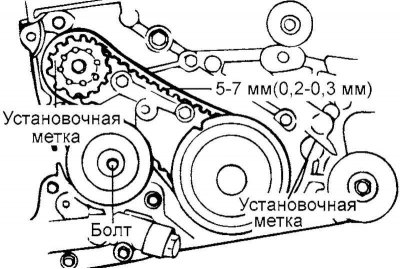
Fig. 2.30. Checking the belt tension
Check the belt tension (Fig. 2.30).
Method 1: Press the middle of the belt with your finger, check whether the deflection arrow matches the nominal value.
Nominal deflection: 5–7 mm.
Method 2: Check the belt tension with a tension gauge.
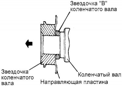
Fig. 2.31. Installing the belt guide and crankshaft sprocket "A"
Install the belt guide and crankshaft sprocket "A". The orientation of the parts is shown in Figure 2.31.
Caution! If the guide is not installed correctly, the belt will break.
Install the special washer and the crankshaft sprocket mounting bolt. Tighten the bolt to the specified torque.
Crankshaft sprocket bolt tightening torque: 110–130 Nm.
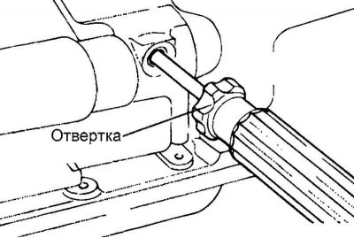
Fig. 2.32. Installing a screwdriver to secure the balance shaft
Insert a screwdriver into the plug hole on the left side of the block to secure the balance shaft (Fig. 2.32).
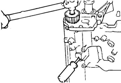
Fig. 2.33. Installing the oil pump sprocket
Install the oil pump sprocket (Fig. 2.33).
Tighten the fastening nut to the specified torque. Tightening torque of the oil pump sprocket: 50–60 N·m.
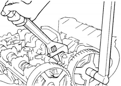
Fig. 2.34. Installing camshaft sprockets
Install the camshaft sprockets and tighten the mounting bolts to the specified torque (Fig. 2.34).
Tightening torque of the camshaft sprocket mounting bolt: 80–100 N·m.
Install the automatic tensioner.
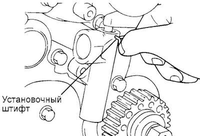
Fig. 2.35. Fixing the automatic tensioner pusher in the housing with a suitable pin
Caution! Before installation, secure the automatic tensioner pusher in the housing with a suitable pin (Fig. 2.35).
Note: The pusher is fixed in three stages.
Note: 1. Install the automatic tensioner in a vice without distorting it. Install a spacer washer under the tensioner body.
Note: 2. Slowly insert the pusher into the housing until the holes in the housing and pusher are aligned.
Note: 3. Secure the pusher with a suitable pin.
Caution: Do not remove the tappet retaining pin until the timing belt has been installed.
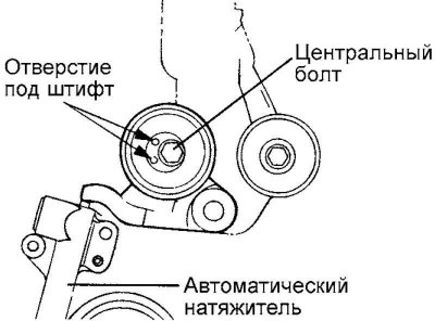
Fig. 2.36. Installing the tensioner roller
Install the tensioner roller on its lever (Fig. 2.36).
Tighten the mounting bolt to the specified torque.
Tensioner roller tightening torque: 43–55 N·m.
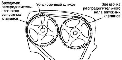
Fig. 2.37. Alignment of camshaft sprocket marks with benchmarks
Align the camshaft sprocket marks with the benchmarks when setting the piston of cylinder No.1 to TDC of the compression stroke (Fig. 2.37).
Note: If the timing marks on the camshafts do not match the reference marks, turn the shaft in the desired direction, but not more than two sprocket teeth, since then the valve and piston come into contact.
Note: If more than two teeth need to be turned, carefully turn the crankshaft counterclockwise approximately 45 degrees. Return the crankshaft to its original position.
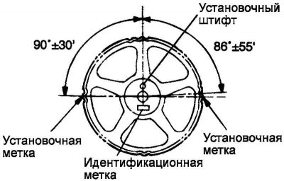
Fig. 2.38. Star identification mark
Note: Check that the camshaft sprocket identification marks match the engine displacement (Fig. 2.38).
Check the alignment of the crankshaft timing mark with the reference mark.
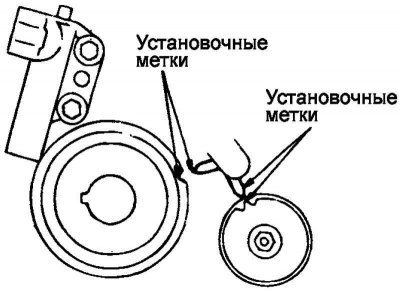
Fig. 2.39. Installation marks
Check the alignment of the oil pump timing mark with the reference mark (Fig. 2.39).
Place the belt on the tensioner pulley, working counterclockwise, starting from the crankshaft sprocket. Hold the belt on the tensioner pulley.
While tensioning the belt, place it on the oil pump sprocket.
Place the belt on the guide roller.
Place the belt on the intake camshaft sprocket.
Turn the exhaust camshaft clockwise one tooth until the timing mark on the sprocket aligns with the top plane of the cylinder head. Tighten the belt with both hands and place it on the exhaust camshaft sprocket.
Rotate the automatic tensioner pulley until all belt slack is taken up. Temporarily tighten the pulley bolt.
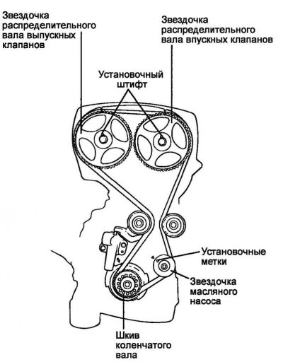
Fig. 2.40. Alignment of installation marks with benchmarks
Check the alignment of all installation marks with the reference points (Fig. 2.40).
Remove the automatic tensioner push rod retainer.
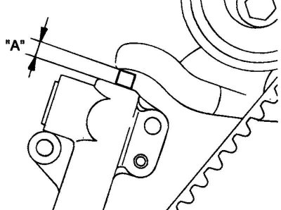
Fig. 2.41. Measuring the protrusion "A" of the tensioner pusher
Turn the crankshaft two revolutions clockwise. Pause for 15 minutes. Measure the protrusion "A" of the tensioner pusher (the distance between the lever and the tensioner housing) (Fig. 2.41).
Make sure the performance meets the technical requirements.
Nominal value: 6-9 mm.
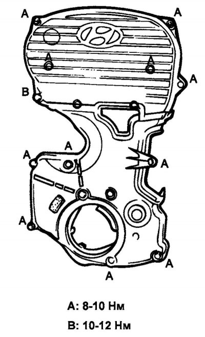
Fig. 2.42. Installing the timing belt covers
Install the timing belt covers (Fig. 2.42).