
Withdrawal

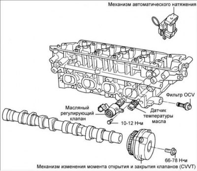
1. Remove the automatic chain tensioner.
2. Remove the camshaft bearing caps and chain.
3. Remove camshafts.
4. Remove the mechanism for changing the moment of opening and closing the valves (CVVT). Secure the hexagonal wrench end of the camshaft in a vise.
Attention! Be careful not to damage the camshaft. Turn out a bolt of fastening CVVT.

5. Remove oil control valve (OCV).
6. Remove the OCV filter.
7. Remove the oil temperature sensor (OTS).
Examination
Do not reuse a dropped valve timing mechanism (CVVT), because it can be deformed.
1. Do not disassemble the mechanism for changing the timing of opening and closing valves (CVVT).
2. When installing a mechanism for changing the moment of opening and closing valves (CVVT) you need to use a special tool.
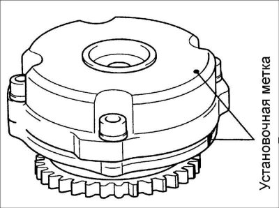
The mechanism for changing the moment of opening and closing valves (CVVT)
1. Secure the hexagonal wrench portion of the camshaft in a vise. Be careful not to damage the camshaft.
2. Make sure that the mechanism for changing the moment of opening and closing the valves (CVVT) does not rotate on the camshaft.
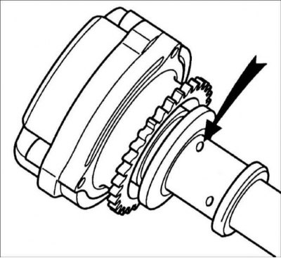
3. Seal all openings of the mechanism for changing the moment of opening and closing valves with adhesive tape (CVVT), except for one indicated by an arrow in the figure.
4. Apply compressed air to the hole at a pressure of approximately 100 kPa.
- The mechanism for changing the moment of opening and closing valves (CVVT) must turn without any external force.
- Supplying air at a higher pressure may cause the locking pin to lock (lack of pressure).
5. While performing the step 4, grasp the mechanism for changing the opening and closing of the valves (CVVT) and turn it in the forward direction.
- After disconnection of the locking pin, the mechanism for changing the moment of opening and closing the valves (CVVT) must move freely in the forward direction.
- Movement of the mechanism for changing the moment of opening and closing the valves (CVVT) from the maximum lag position to the maximum advance position is 20°.
6. If necessary, replace the mechanism for changing the moment of opening and closing the valves (CVVT), otherwise, turn it in the retard direction until the locking pin locks.
Oil control valve (OCV)
1. Using an ohmmeter, measure the internal resistance of the oil control valve (OCV). Resistance: 6.9 - 7.9 ohms at 20°C.
2. If the resistance is not as specified, replace the oil control valve.
3. Check the operation of the oil control valve (OCV).
- Apply voltage to the valve terminals from the battery terminals: - make sure that the coil moves in the forward direction.
- Disconnect the wires from the battery terminals: - make sure the coil returns to its original position.
OCV filter
Check the condition of the filter and the absence of dirt in it. If dirty, clean or replace the filter.
Camshaft (CVVT)
Inlet camshaft lobe height: 44.618 mm
Exhaust camshaft lobe height: 44.518 mm
Minimum allowable height of the intake camshaft cams: 44.518 mm
Minimum allowable height of the camshaft camshafts of the exhaust valves: 44.418 mm
Installation
1. Install the oil temperature sensor (OTS).
2. Install the OCV filter. Tightening torque: 41–51 Nm.
- Keep clean during assembly.
- When reassembling the oil control valve filter (OCV) replace washer.
3. Install oil control valve (OCV). Tightening torque OCV: 10–12 Nm.
- Do not reuse dropped parts.
- Keep foreign material out of the OCV bushing.
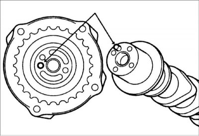
4. Carefully insert the camshaft stud into the hole in the mechanism for changing the opening and closing of the valves (CVVT).
5. After installing the CVVT on the camshaft, screw in the bolt after lubricating the bolt thread with oil.
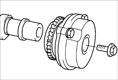
6. Tighten the CVVT mounting bolt on the camshaft.
- Secure the hexagonal wrench end of the camshaft in a vise. Be careful not to damage the camshaft. Bolt tightening torque CVVT: 66–78 Nm.
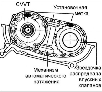
7. Install the chain on the camshaft sprockets as shown in the figure.
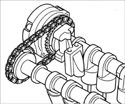
8. Install camshafts and bearing caps.
9. Install the automatic chain tensioner. Tightening torque: 8–10 Nm.
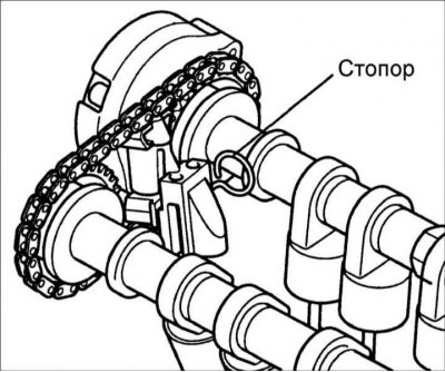
10. Remove the stopper blocking the automatic chain tensioner.