
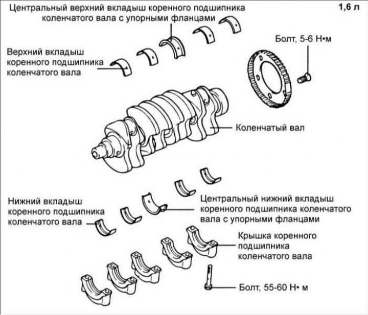
Engine 1.6 l
Withdrawal
1. Remove the toothed belt, front cover, flywheel and oil pan.
2. Remove the rear cover from the cylinder block and the crankshaft rear O-ring.
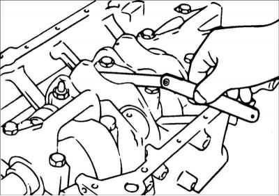
3. Turn away nuts and remove covers of rods.
Attention! Mark the crankshaft main bearing caps in order to install them in their places and in the same position.
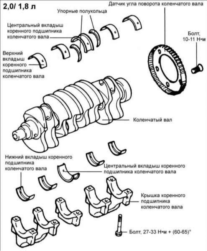
4. Turn out bolts and remove covers of radical bearings of a cranked shaft and a cranked shaft.
5. Remove the crank angle sensor rotor.
Examination
1. Check the crankshaft main and connecting rod bearing journals for wear and wear. Check crankshaft oil holes for blockage.
2. With a micrometer, measure the diameters of the crankshaft journals in two diametrically opposite directions. If there is a taper or ovality, regrind the crankshaft.
Diameter of main journals:
- engines 1.8 and 2.0 l: 57 mm;
- 1.6L engines: 50mm.
Diameter of connecting rod journals: 45 mm
Taper and ovality of the crankshaft journals:
- engines 1.8 and 2.0 l: no more than 0.01 mm;
- engines 1.6 l: no more than 0.005 mm.
Connecting rod and main bearing shells
Check the connecting rod and main bearings for localized corrosion, wear, or other damage. If necessary, replace the liners.
Measuring the clearance of main and connecting rod bearings
To measure the clearance of the main and connecting rod bearings, measure the diameters of the crankshaft journals and the corresponding inner diameters of the bearings.
The clearance value is the difference between the inner diameter of the bearing and the corresponding diameter of the crankshaft journal.
Main bearing clearance:
- engines 1.8 and 2.0 l: 0.028–0.048 mm;
- 1.6L engines: No. 1, 2, 4, 5: 0.022–0.040 mm;
- No. 3: 0.028–0.046 mm.
Connecting rod bearing clearance:
- engines 1.8 and 2.0 l: 0.024–0.044 mm;
- 1.6L engines: 0.018–0.036 mm.
Oil seal rings
Check the front and rear oil seals for damage or wear on the sealing lips. If there are any defects, replace the O-ring.
Bearing caps
After installing the bearing caps, rotate the crankshaft and make sure that it rotates easily and smoothly, and its end play is within the specifications.
Axial play of the crankshaft: 0.06–0.26 mm.
Maximum permissible axial play of the crankshaft: 0.30 mm.
Crank angle sensor rotor
1. Remove the crank angle sensor rotor.
2. Check the crank angle sensor rotor for damage, cracks and wear and replace if necessary.
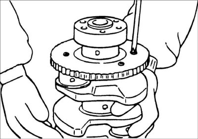
3. Check the clearance between the crank angle sensor rotor and the crank angle sensor. Gap between crank angle sensor rotor and crank angle sensor: 0.5–1.1 mm.
- 1. Measure the installation depth of the sensor, i.e. the distance from the top of the crank angle sensor rotor teeth to the outside of the cover.
- 2. Calculate the difference between the length of the crank angle sensor and its installation depth.
Choice of 1.6L Engine Main Bearings
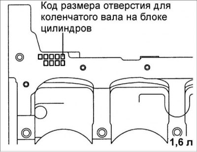
1. Check the crankshaft hole size code in the cylinder block.
Attention! Write down the letter code for the size of the crankshaft hole in the cylinder block. The reading order is from left to right, with the first code corresponding to the size of the front hole in the cylinder block.
Class | Crankshaft bore diameter | Size Code |
A | 54.000–54.006 mm | A |
b | 54.006–54.012 mm | IN |
c | 54.012–54.016 mm | WITH |
2. Check the crankshaft journal diameter size code.
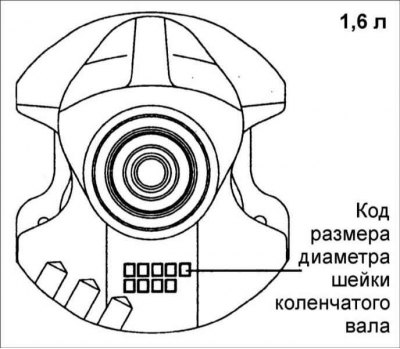
Attention! Record the crankshaft journal size letter code located on the crankshaft counterweight. The reading order is from left to right, with the first code corresponding to the size of the front crankshaft journal.
Diameters of crankshaft journals
Class | Crankshaft bore diameter | Size code |
I | 49.968 - 49.962 mm | A |
II | 49.962 - 49.956 mm | b |
III | 49.956 - 49.950 mm | c |
Thickness of the main bearing shell No. 1, 2, 4, 5 of the crankshaft
Color | Thickness of the crankshaft main bearing shell |
| Yellow | 2.002–2.005 mm |
| Green | 2.005–2.008 mm |
| no color | 2.008–2.011 mm |
| Black | 2.011–2.014 mm |
| Blue | 2.014–2.017 mm |
No. 3 main bearing shell thickness (central) crankshaft
Color | Thickness of the crankshaft main bearing shell |
| Yellow | 1.999 - 2.002 mm |
| Green | 2.002 - 2.005 mm |
| no color | 2.005 - 2.008 mm |
| Black | 2.008 - 2.011 mm |
| Blue | 2.011 - 2.014 mm |
3. According to the table, select the thickness of the main bearing shells.
Installation
1. Install the upper main bearing shells to the engine block. When reinstalling the earbuds, install them in the same places they were before removal.
2. Before installing the crankshaft, apply a thin film of clean engine oil to all sliding surfaces. Install the crankshaft onto the main bearing shells in the cylinder block.
3. Install the remaining main bearing shells into the crankshaft main bearing caps. Install the crankshaft main bearing caps as marked, with the arrow on each cap pointing towards the crankshaft pulley. In a certain sequence, in 2 or 3 stages, tighten the crankshaft main bearing cap bolts in the following order: center, No. 2, No. 4, front and rear.
Torque:
- Main bearing caps:
- 1.8 and 2.0 l engines: 27–33 Nm tighten by an angle (60–65) °;
- 1.6L engines: 55–60 Nm.
- Connecting rod bearing caps:
- engines 1.8 and 2.0 l: 50–53 Nm;
- 1.6L engines: 32–35 Nm.

4. Turn the crankshaft and check that it rotates easily and smoothly. Using a feeler gauge inserted between the thrust half ring and the crankshaft, check the crankshaft end play.
Axial play of the crankshaft:
- engines 1.8 and 2.0 l: 0.06–0.260 mm;
- 1.6L engines: 0.05–0.175 mm.
Axial play of the connecting rod: 0.10–0.25 mm.
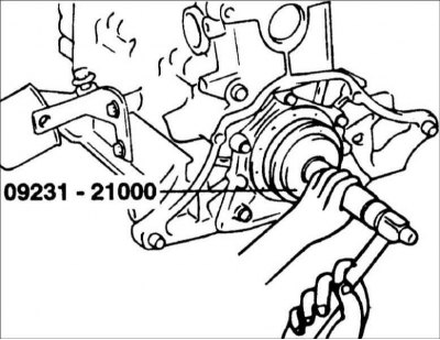
5. Lubricate the outside of the new rear O-ring with engine oil. Using the special tool 09231-22000, install the o-ring until it stops in the rear cover slot.
6. Install the O-ring cover, gasket and tighten the bolts. At installation grease working edges and an external surface of a sealing ring with pure engine oil.
7. Install the connecting rod caps.
8. Install the flywheel, front cover, oil pan and toothed belt.