
1.6L engines
Withdrawal
Connecting rod cap
Attention! Keep the connecting rod caps with the appropriate connecting rods for proper reinstallation in the engine cylinders.
1. Turn away nuts and remove a cover of a rod and the bottom loose leaf of a rod bearing. For protection of necks of a cranked shaft put on bolts of fastening of covers of rods pieces of a rubber or plastic tube.
2. Use a block of wood or a hammer handle to push the piston and connecting rod out of the cylinder.
Removal and installation of a piston pin
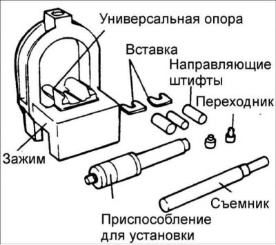
1. Special tools 09234-33001 and 09234-33002 must be used to disassemble and reassemble the piston and connecting rod.
2. Install universal supports in the clamp between the connecting rod and piston.
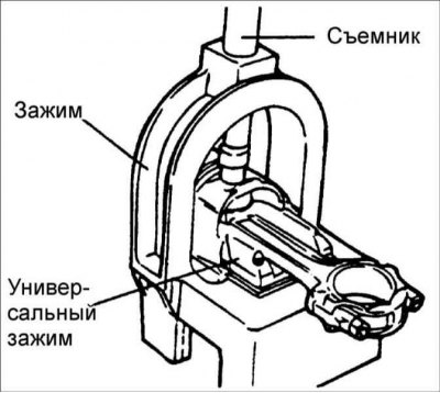
3. Insert the puller through the hole in the arch of the clamp.
Attention! Insert the clamp with the piston, connecting rod and puller under the press slider.
4. With a puller, press the piston pin out of the piston.
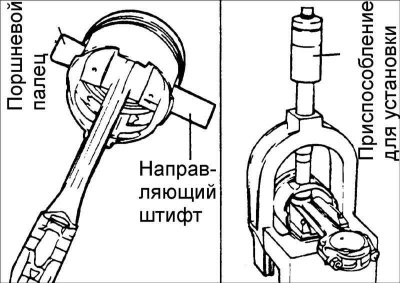
5. Install the guide pins through the piston into the connecting rod, and install the piston pin on the other side of the piston.
Attention! The guide pins determine the position of the connecting rod in the piston. Once the piston, connecting rod, piston pin and piston pin insertion tool are installed, the guide pins also determine their position in the clamp. If the drive pins are too small, the piston will not be centered in the fixture and the clip and/or fixture may be damaged.
6. Install the piston assembly on the clamp with the guide pin supporting the connecting rod in the piston pin. Make sure the piston slides over the clamp until the drive pin makes contact with the fork insert.
7. Check the correct positioning of the piston and connecting rod and, rotating the knurled nut, secure the numbered sleeve on the shaft.
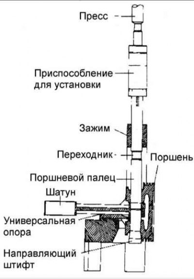
8. Insert the shaft through the hole in the arch of the clamp. Press the piston pin into the connecting rod until the sleeve on the shaft contacts the top of the arch of the clamp, and the pilot pin should fall out of the piston.
Warning! The piston pin pressing force should not exceed 350–1350 kg on 1.8 and 2.0 liter engines and 1250±500 kg on a 1.6 liter engine.
Examination
Piston and piston pins
1. Check the outer surface of the piston for damage, wear, or uneven wear. If necessary, replace the piston.
2. Check each piston ring for damage and uneven wear. If necessary, replace piston rings. When replacing a piston, the piston rings must also be replaced.
3. Check the piston pin by inserting it into the piston bore. The piston pin should smoothly enter the piston when pressed by hand (at room temperature).
Piston rings
1. Insert a new piston ring into the piston groove and use a feeler gauge to measure the gap between the piston ring and the groove wall. If the clearance exceeds the maximum allowable value, replace the piston.
Gap between piston ring and piston groove:
First compression ring:
- engines 1.8 and 2.0 l: 0.04–0.08 mm;
- 1.6L engines: 0.04–0.085 mm.
Second compression ring:
- engines 1.8 and 2.0 l: 0.03–0.07 mm;
- 1.6L engines: 0.04–0.085 mm.
2. Measure the piston ring gap by manually inserting the piston ring into the engine cylinder. Use the piston crown to push the piston ring into the bottom of the cylinder. Use a feeler gauge to measure the clearance in the piston ring lock.
Piston ring clearance:
- First compression ring:
- engines 1.8 and 2.0 l: 0.23–0.38 mm;
- 1.6L engines: 0.15–0.30 mm.
- Second compression ring:
- engines 1.8 and 2.0 l: 0.33–0.48 mm;
- 1.6L engines: 0.30–0.45 mm.
- Oil ring:
- engines 1.8 and 2.0 l: 0.20–0.60 mm;
- 1.6L engines: 0.20–0.70 mm.
Maximum allowable clearance:
- First and second compression rings: 1.0 mm.
- Oil scraper ring: 1.0 mm.
Attention! The marking is applied to the upper part of the piston ring, from the side of the lock.
Connecting rods
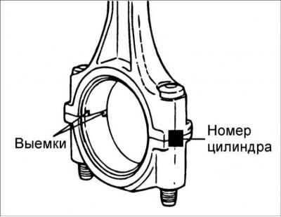
1. When installing, make sure the connecting rod and connecting rod cap match the cylinder number they are installed in. When installing a new connecting rod, make sure that the marks that determine its position are on the same side as the marks on the other connecting rods.
2. Replace the connecting rod if there is damage on both bearing surfaces. Also replace the connecting rod if there is wear or damage to the piston pin mating surface.
Selection of engine pistons 1.6 l
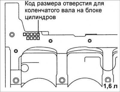
1. Check the cylinder bore size code located on the face of the cylinder block.
Class | Cylinder inner diameter | Size code |
A | 76.5–76.51 mm | A |
B | 76.51–76.52 mm | B |
C | 76.52–76.53 mm | C |
2. Check the piston diameter size code located on the piston crown.
Attention! The piston diameter size code is stamped on the piston crown.
Class | Cylinder inner diameter | Size code |
A | 76.465–76.475 mm | A |
B | 76.475–76.485 mm | B |
C | 76.485–76.495 mm | C |
3. Select a piston whose diameter matches the cylinder class. Clearance between piston and cylinder: 0.025–0.045 mm.
Installation
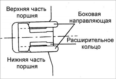
1. Install expansion ring.
2. Install the top side guide. To install the side guide, first place one end of the side guide between the wall of the piston ring groove and the expansion ring, push it in, then press it all the way into the piston groove.
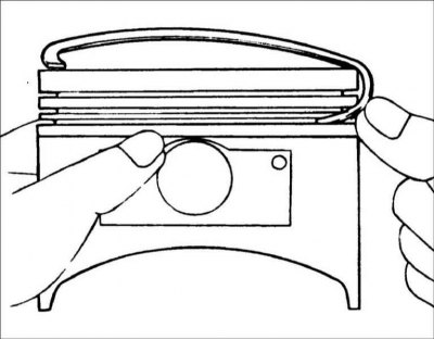
3. Install the lower side rail in the same way.
Attention! Do not use piston ring pliers when installing the side guide.
4. Apply a thin layer of engine oil to the piston and piston rings.
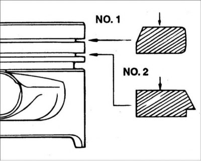
5. Using pliers to expand the piston rings, install compression ring No. 2.
6. Using pliers to expand the piston rings, install compression ring No. 1.
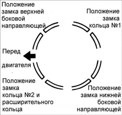
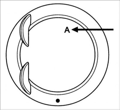
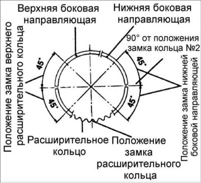
7. Position the piston ring locks as shown.
8. Use the special tool to compress the piston rings on the piston. Install the piston with piston rings over the first cylinder, with the mark on the piston facing the front of the cylinder block. Using a hammer handle, press the piston into the cylinder so that the lower end of the connecting rod rests on the crankshaft journal.
9. Establish the top loose leaves of radical bearings on the block of cylinders of the engine. When reinstalling the earbuds, install them in the same places they were before removal.
10. Install the main bearing shells in the crankshaft main bearing caps.
11. Be convinced that marks on the piston and a rod are directed to a forward part of the block of cylinders.
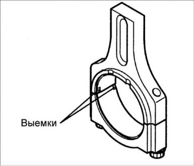
12. When installing a new connecting rod, make sure that the grooves for the bearing shell are on one side.
13. Tighten bolts and nuts of fastening of covers of rods.
- lubricate the threads of nuts and bolts with engine oil;
- Torque tighten the bolts and nuts securing the connecting rod caps.
Torque:
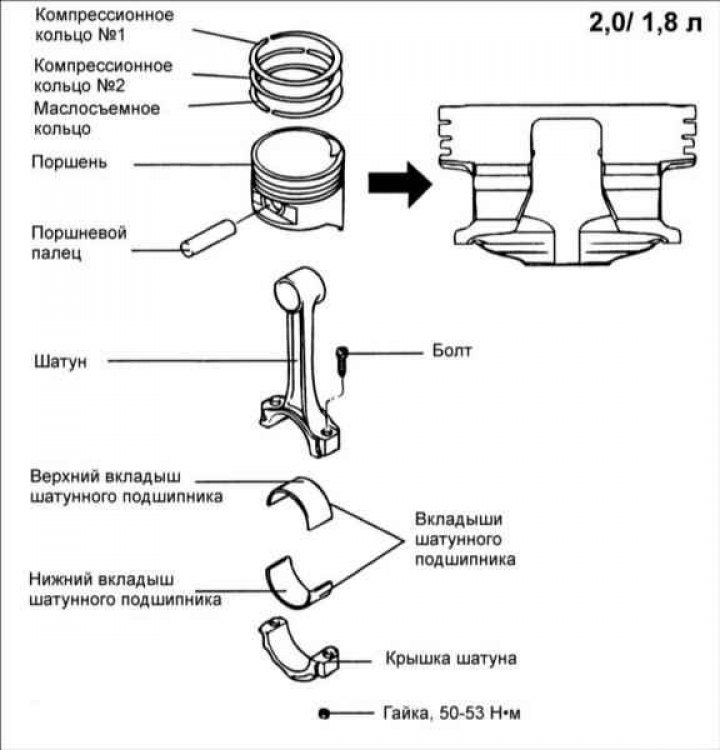
- engines 1.8 and 2.0 l: 50–53 Nm;
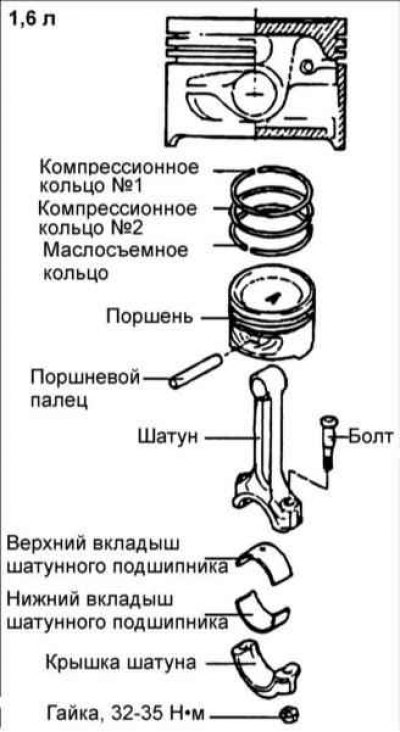
- 1.6L engines: 32–35 Nm.
Warning! Do not reuse the connecting rod cap bolts more than three times.
14. With a feeler gauge inserted between the connecting rod and the crankshaft, measure the side clearance of the connecting rod. Rated connecting rod side clearance: 0.10 - 0.25 mm. Maximum allowable gap: 0.40 mm
15. Install the oil filter.
16. Install the oil pan.
17. Install the cylinder head.