


Removal
1. Remove the timing belt, front cover, wheel, cylinder head and oil pan.
2. Remove the rear plate and rear oil seal.
3. Remove the lower connecting rod head caps.
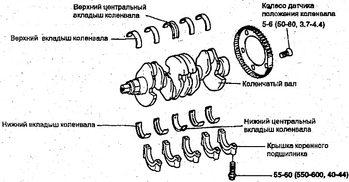
Note: Mark the crankshaft main bearing caps so that you can reinstall them in the same position.
4. Remove the main bearing caps and crankshaft. Arrange the liners according to the bearing cap numbers.
5. Remove the crankshaft position sensor wheel.
Examination
Crankshaft
1. Check the crankshaft main and connecting rod journals for damage, wear and cracks. Also check that the holes are not clogged. Repair or replace any defective parts.
2. Check the crankshaft main and connecting rod journals for ovality and taper.
Standard size:
- The outer diameter of the crankshaft journal is 50 mm
- The outer diameter of the crank pin is 45 mm
- Ovality and taper of main and brass journals of the crankshaft - 0.01 mm and less
Main and connecting rod bearings
Visually inspect each bearing for delamination, melted areas, scoring, etc. Replace defective bearings.
Measuring oil clearances
Check the oil clearances by measuring the outside diameter of the main and connecting rod journals of the crankshaft and the inside diameter of the bearings. The clearance value is obtained by determining the difference between the measured inside and outside diameters.
Oil clearance of main journals:
- No. 1, 2, 4, 5 — 0.028-0.046 mm
- No. 3 — 0.034-0.052 mm
- Oil clearance of connecting rod journals - 0.024-0.042 mm
Measuring oil clearances with a plastic template
The plastic template can be used to measure gaps as follows.
1. Remove oil, dirt and grease from the bearings and crankshaft journals.
2. Cut a piece of plastic template to a length equal to the width of the bearing and place it along the axis of the journal away from the lubrication holes.
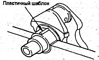
3. Install the bearing shells and caps and tighten them to the specified torque. Do not rotate the crankshaft during this operation. Remove the bearing caps. Using the scale printed on the template package, measure the thickness of the plastic template. If the clearance exceeds the permissible value, the shell must be replaced or a shell of a reduced size must be used. When installing a new crankshaft, use shells of the nominal size. If the clearance is not equal to the standard value even after replacing the shell, the journals can be ground to the recommended reduced size and shells of the same size can be used.
Seal
Check the front and rear oil seals for damage and worn edges. Replace the defective seal.
Installation
1. Install the upper main bearing into the cylinder block. If reusing the main bearing during disassembly, mark it to facilitate its reinstallation.
2. Install the crankshaft. Apply engine oil to the journals.
3. Install the bearing caps and tighten the bolts to the required torque in the following sequence: center, #2, #4 front and rear caps. The cap bolts must be tightened evenly in 2-3 steps.
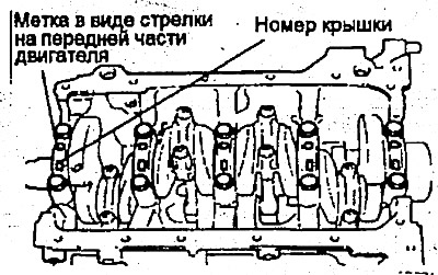
The covers must be installed with the arrows pointing towards the front of the engine. Make sure the covers are positioned correctly according to their numbers.
Tightening torque:
- Main bearing cap bolt - 55-60 Nm
- Connecting rod cap bolt - 35-38 Nm
4. Make sure the crankshaft rotates freely and has adequate clearance
- Crankshaft axial clearance - 0.05-0.175 mm
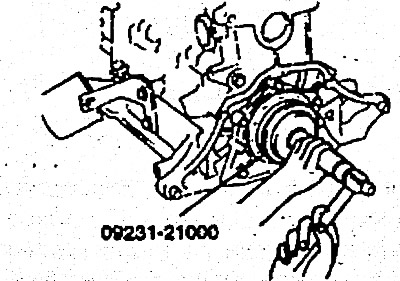
5. Install the rear crankshaft bearing oil seal. Use the special tool to install the rear crankshaft bearing oil seal (09231-21000), as shown. Press the seal in carefully.
The original text is published on the website: HYUNDAIBOOK.RU
6. Install the rear bearing seal gasket and housing.
7. Install the back plate and tighten the bolts.
8. Install the connecting rod caps.
9. Install the flywheel, front cover, oil pan and timing belt.