
HyundaiBook.ru
Repair Chevrolet Repair Honda Repair Toyota Repair Land Rover Repair VAZ Repair Renault Repair Nissan
English Русский
Български
Беларускі
Український
Српски
Hrvatski
Română
Polski
Slovenský
Magyar
ArticlesSitemapContacts  


  Accent   Elantra   Getz   Grandeur   Sonata   Santa Fe   Tucson   Others
Accent 1 (1994-1999) Accent 2 (1999-2005) Accent 3 (2005-2010)
  • Main
  • Accent
  • X3 (1994-1999)
  • Power unit
  • SOHC engines
  • Valves and valve springs — removal, inspection and installation

Valves and valve springs — removal, inspection and installation (Hyundai Accent X3)

0
Contents: Removal ⇓ Examination ⇓ Installation ⇓
Valves and valve springs — removal, inspection and installation


Removal


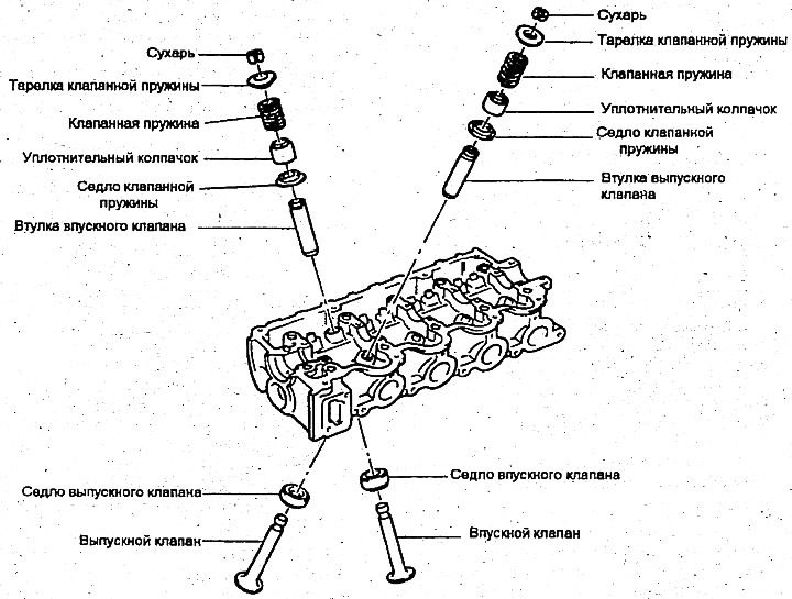
1. Using a special tool to compress the valve springs (09222-28000, 09222-28100), remove the cracker. Next, remove the upper valve spring plate, valve spring, lower plate and valve.

Note: Keep these dividers in the order in which they should be installed in their original places.


2. Use pliers to remove the sealing cap (do not reuse it).
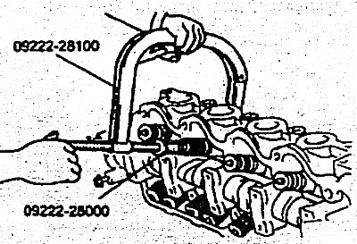
2. Use pliers to remove the sealing cap (do not reuse it).


Examination


Valves


Check each valve for wear, damage, head destruction and stem in zone B. Repair or correct if necessary. If end A of the stem is worn, restore its surface. This direction should be minimal. Also restore the surface of the valve working chamfer. If the valve edge height is less than the permissible limit, replace the valve.
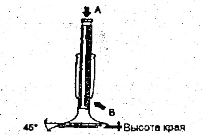
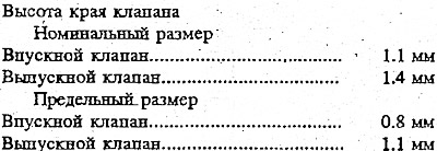

Check each valve for wear, damage, head destruction and stem in zone B. Repair…


Check each valve for wear, damage, head destruction and stem in zone B. Repair…


Valve springs


1. Check the length of the spring in the assembled state and its extension. If it exceeds the permissible limits, replace the spring.

2. Check the parallelism of the ends of each spring. If it exceeds the established limits, replace the spring.
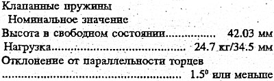
2. Check the parallelism of the ends of each spring. If it exceeds the…


Valve bushings


Check the clearance between the valve stem and the bushing. If it exceeds the specified limits, replace the valve bushing with the next size bushing.
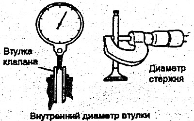
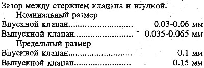
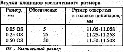
Check the clearance between the valve stem and the bushing. If it exceeds the…


Check the clearance between the valve stem and the bushing. If it exceeds the…


Check the clearance between the valve stem and the bushing. If it exceeds the…

Valve seat


Check the valve seat for signs of overheating and proper contact with the valve seat face. Repair or replace the valve seat if necessary.

Before repairing the seat, check the valve bushing for wear. If the bushing is worn, replace it, then repair the seat. Repair the valve seat using a valve seat grinder or a milling cutter.
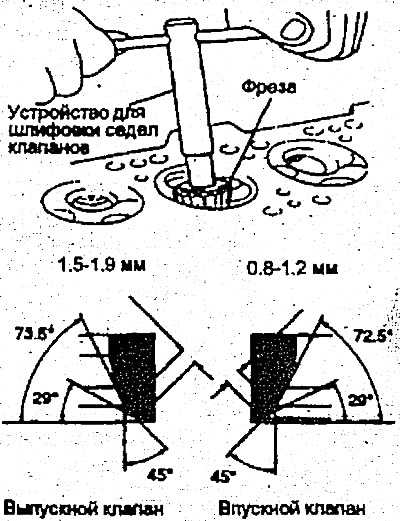


Before repairing the seat, check the valve bushing for wear. If the bushing is…


Valve seat replacement procedure


1. A valve seat that is worn beyond the permissible limits should be replaced after cutting off most of the seat wall using a valve seat grinder as shown in the figure.
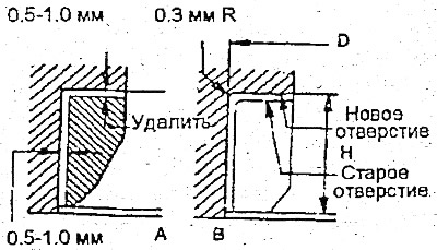
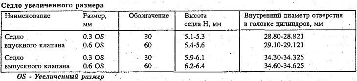
1. A valve seat that is worn beyond the permissible limits should be replaced…


1. A valve seat that is worn beyond the permissible limits should be replaced…

2. After removing the seat, use a reamer or milling cutter to process the hole for the seat. Process to the size specified in the table.


3. Heat the cylinder head to approximately 250°C and press in an oversized seat.

Valve Bushing Replacement Procedure


The valve sleeve is installed using a press fit. Using a valve sleeve installation device. (09221-22000) or using the appropriate tool, replace the valve sleeve in the following order:

1. Using the valve sleeve installer pusher, push the valve sleeve towards the cylinder block using a press.

2. Machine the valve bushing hole in the cylinder head to the increased size of the new valve bushing.
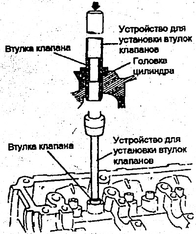
2. Machine the valve bushing hole in the cylinder head to the increased size of…


3. Using a valve guide installer or appropriate tool, press the valve guide into a press fit. Using a valve guide installer, it is possible to press the valve guide to a specified height. The valve guide must be installed from the top of the cylinder head. Note that the intake and exhaust guides have different lengths (42.7 mm for the intake valve and 39.1 mm for the exhaust valve).

The oversized saddle should be at normal room temperature before installation. After installing the new saddle, treat its surface as just described above.

4. After installing the valve bushings, insert new valves into them and check the clearance between them.


5. Each time the valve bushings are replaced, check the nature of the valve contact with the seat and, if necessary, restore the seat surface.
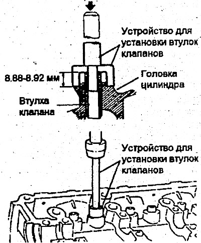
5. Each time the valve bushings are replaced, check the nature of the valve…


Installation


Note:
1) Clean all parts before assembly.
2) Use engine oil to lubricate rotating and sliding parts.


1. After installing the lower spring plate, press the sealing cap onto the valve sleeve. To install it, push the cap on by gently rotating the valve sealing cap installer (09222-22000).

The sealing cap is installed in the desired position using a special tool. If the sealing cap is not positioned correctly, the lug and its internal hole may be eccentric and oil may leak into the valve sleeve. Do not rotate the cap when installing. Do not use old sealing caps.
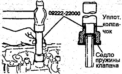
The sealing cap is installed in the desired position using a special tool. If…


2. Apply engine oil to each valve. Insert the valves into the bushings without forcing the valve stem through the sealing cap. After installation, check that the valve moves easily.


3. Install the valve springs and their upper retainers. The valve springs should be installed with the varnished side facing the upper retainer.
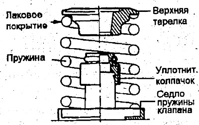
3. Install the valve springs and their upper retainers. The valve springs…


4. Using a valve spring compressor (09222-28000; 09222-28100), compress the spring. Be careful not to deform the top of the plate with the sealing cap. Then install the crackers. After installing the valves, make sure the crackers are installed correctly.

5. Install the cylinder head.
This article is available at russian, bulgarian, belarusian, ukrainian, serbian, croatian, romanian, polish, slovak, hungarian
This article has been reviewed by: Konstantin Smirnov
Add to social network:

Previous
Accent 1: SOHC engines
Next

Cylinder head — removal, inspection and installation
Camshaft — removal, inspection and installation
Rocker arms, shafts and hydraulic clearance compensator
Timing belt — removal, inspection and installation
Engine and gearbox assembly
Front cover, oil pump — removal, inspection and installation
Piston and connecting rod — removal, inspection and installation
Crankshaft — removal, inspection and installation
Flywheel — removal, inspection and installation
Cylinder Block — Removal and Inspection
We recommend other articles on the topic of Hyundai manuals:

Valve springs, crackers and seals — replacement (method without… Hyundai Elantra 1 (1990-1995, petrol)
Valve tappet failures Hyundai Getz (2002-2011)
Cylinder Heads, Valves and Valve Springs — Removal and… Hyundai Sonata 3 (1993-1998)
Checking the radiator cap valves Hyundai Santa Fe 2 (2007-2012, petrol)
Checking and adjusting valve clearances Hyundai Tucson 1 (2005-2010)
Checking the radiator cap valves Hyundai Matrix (2001-2010, petrol)

Link in different formats to this article

Visitor comments
No comments yet


How much will 30 + 42 ?


Accent 3 (2005-2010) 
  • General information
  • User manual
  • Maintenance
  • Power unit
  • Engine repair
  • Cooling and lubrication system
  • Power and exhaust system
  • Engine electrical equipment
  • Engine management
  • Transmission
  • Clutch
  • Mechanical gearbox
  • Automatic gearbox
  • Chassis
  • Front suspension
  • Rear suspension
  • Wheels and tires
  • Steering
  • Brake system
  • Body
  • Exterior (external elements)
  • Interior (internal elements)
  • Heating and ventilation
  • Electrical equipment
  • Equipment and devices
  • Electrical circuits
Accent 2 (1999-2005) 
  • User manual
  • Control devices
  • Starting engine and driving
  • Troubleshooting
  • Power unit
  • SOHC engines
  • DOHC engines
  • Lubrication system
  • Cooling system
  • Decreased toxicity
  • Fuel system
  • Ignition system
  • Transmission
  • Clutch
  • Mechanical gearbox
  • Automatic gearbox
  • Axles and drive shafts
  • Chassis
  • Car suspension
  • Steering
  • Brake system
  • Body
  • Exterior (external elements)
  • Interior (internal elements)
  • Air conditioning system
  • Electrical equipment
  • Equipment and devices
  • Power devices
Accent 1 (1994-1999) 
  • General information
  • Maintenance
  • Power unit
  • SOHC engines
  • DOHC engines
  • Cooling system
  • Intake and exhaust systems
  • Fuel supply (1.3 l, injection)
  • Fuel supply (1.5 l, injection)
  • Fuel supply (carburetor)
  • Transmission
  • Clutch
  • Manual gearbox
  • Automatic gearbox
  • Drive shafts
  • Chassis
  • Car suspension
  • Steering
  • Brake system
  • Body
  • Body elements
  • Electrical equipment
  • Equipment and devices
  • Electrical circuits
HyundaiBook.ru © 2018-2026 · Mobile version · Sitemap: EN BG BY UA RS HR RO PL SK HU · Administration · Site search · Hyundai owners Accent 1 · Accent 2 · Accent 3 · Elantra 1 · Elantra 2 · Elantra 3 · Getz · Sonata 3 · Sonata 4 · Santa Fe 2 · Tucson 1 · Tucson 2 · Matrix ·
This site uses cookies to optimize its functionality. By continuing, you agree to our terms.