Removal
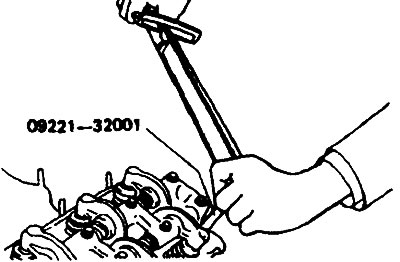
1. Using a special key (09221-32001), loosen the cylinder head mounting bolts.
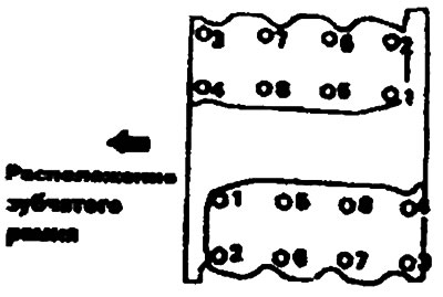
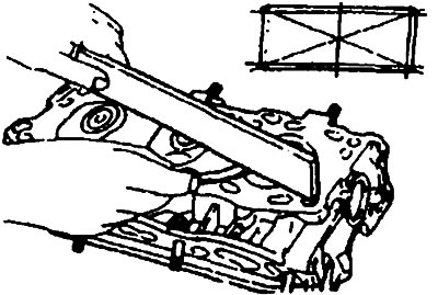
2. Gradually loosen the cylinder head bolts in the sequence shown in the figure.
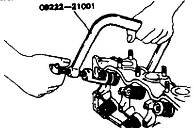
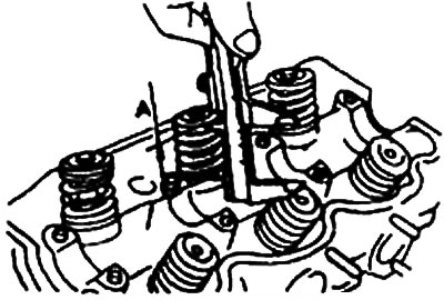
3. Using a special tool (09222-21001), using a valve spring compressor, remove the crackers.
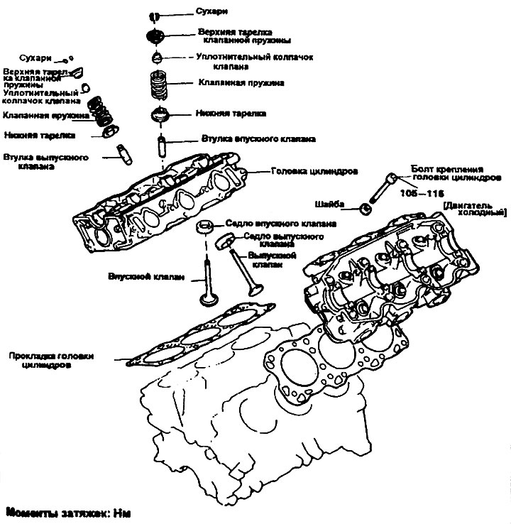
4. Lay out these parts in such an order that they will fall into place when assembled.
 |
 |
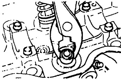
5. Using pliers, remove the valve sealing caps.
Note: Do not reuse sealing caps.
Examination
Cylinder head
1. Completely remove scale, sealing material and crankcase. After cleaning the oil passages, blow them out with compressed air.
2. Visually inspect the cylinder head for cracks, damage and coolant leaks.
3. Using a straight edge ruler and a feeler gauge, check the flatness of the lower surface of the cylinder head as shown in the figure.
Cylinder head flatness deviation:
- Nominal value - max 0.05 mm
- Limit value - 0.20 mm
Valve bushings
Check the clearance between the valve stem and the bushing. If the clearance exceeds the permissible limit, replace the valve bushing.
Clearance between valve stem and bushing:
- Nominal value:
- Inlet valve - 0.03-0.06 mm
- Exhaust valve - 0.05-0.09 mm
- Limit value:
- Inlet valve - 0.10 mm
- Exhaust valve - 0.15 mm
Valve
1. Replace the valve if its stem is worn (worn or damaged). Also replace the valve if the end of the stem (the surface that contacts the automatic lash adjuster) has dimples.
2. Check the contact strip of the valve working chamfer and, if necessary, grind it or replace the valve.
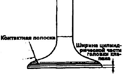
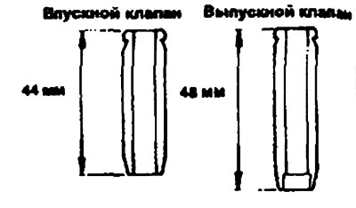
3. Replace the valve if the size of the cylindrical part of its head is less than the minimum value.
Size of the cylindrical part of the valve head:
- Nominal value:
- Inlet valve - 1.2 mm
- Exhaust valve - 2.0 mm
- Limit value:
- Inlet valve - 0.7 mm
- Exhaust valve - 1.5 mm
Valve springs
1. Check the free height of each spring and replace it if necessary.
2. Using a square, measure the deviation of each spring from vertical. If the spring deviates significantly from vertical, replace it.
Valve spring:
- Nominal value:
- Height in free state - 50.5 mm
- Force - 32.9 kgf/40.4 mm
- Deviation from verticality - max. 2°
- Limit values:
- Height in free state - 49.5 mm
- Force - 32.9 kgf/41.4 mm
- Deviation from verticality - max. 4°
Restoration of valve seats
1. Before restoring the seats, check the bushings for wear. If necessary, replace worn bushings, then restore the valve seats.
2. After restoring the valve seats, use a valve seat cutter and extension.
3. After restoration, the valve and its seats should be lightly lapped using lapping paste.
4. Check the valve seats for pits. If the pits are larger than the permissible size, replace the seat with a new one.
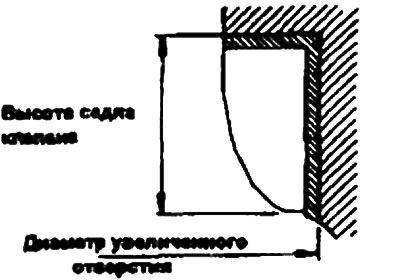
5. After installing the lower plate, valve spring, upper plate and crackers, measure the height of the valve spring in the installed position. The measurement results allow you to determine the size of the valve seat cavities.
Height A of valve spring in installed position (for intake and exhaust valves):
- Nominal value - 40.4 mm
- Limit value - 41.4 mm
Replacing the valve seat
1. Cut the inside surface of the valve seat to reduce its thickness, then remove the seat.
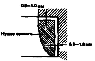
2. Match the diameter of the valve seat hole in the cylinder head to the diameter of the oversized seat for a press fit.
3. Heat the cylinder head to approximately 250°C and press the oversized seat into the cylinder head bore at normal temperature.
4. Treat the valve seat as shown in the figure.
5. Using lapping paste, lap the valve.
Dimensions of repair valve seats
| Name | Size, mm | Size mark | Height H of valve seat, mm | Inner diameter of the hole in the cylinder head, mm |
| Intake valve seat | 0,3 O.S.
0,6 O.S. | 30
60 | 7,9-8,1
8,2-8,4 | 44,300-44,325
44,625-44,625 |
| Exhaust valve seat | 0,3 O.S.
0,6 O.S. | 30
60 | 7,9-8,1
8,2-8,4 | 38,300-38,325
38,625-38,625 |
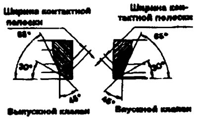
Valve seat contact strip width:
- Inlet valve - 0.9-1.3 mm
- Exhaust valve - 0.9-1.3 mm
 |
 |
Replacing valve bushings
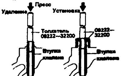
1. Using a special tool (09222-32200), press out the old valve sleeve towards the bottom of the cylinder head.
2. Ream the valve sleeve bore to accommodate the press fit of the new oversized sleeve.
Valve repair bushings
| Size, mm | Size mark | Cylinder head hole diameter, mm |
| 0,05 O.S. | 5 | 13,050-13,068 |
| 0,25 O.S. | 25 | 13,250-13,268 |
| 0,50 O.S. | 50 | 13,500-13,518 |
3. Using a special tool (09222-32200), press in the valve sleeve. The valve sleeve must be pressed in from the top side of the cylinder head. Remember that the valve sleeves have different lengths.
4. After pressing the bushings, insert new valves into them and check the clearance.
5. After replacing the valve bushings, check the correct contact between the valve working chamfer and the seat.
Note: Do not install when changing bushings of the same size.
 |
 |
Installation
1. Install the lower valve spring retainers.
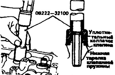
2. Using a special tool (09222-32100) place the sealing caps back into place.
Note:
- Do not reuse old sealing caps.
- Incorrect installation of the sealing cap may cause oil to leak down the valve sleeve.
3. Apply engine oil to each valve. Insert the valves into the bushings: Do not force the valves into the sealing caps.
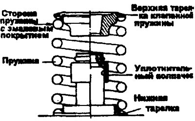
4. Valve springs should be installed with the coated side facing the top plate.
5. Using a special device (09222- 21001), compress the spring and install the crackers. After installing the valves, check the correct installation of the crackers before releasing the spring of their device.
 |
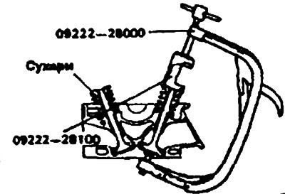 |
Note: When compressing the spring, make sure that the sealing cap is not pressed against the bottom of the upper spring plate.
6. Clean the bottom surface of the cylinder head and the top surface of the block itself.
7. Check the identification marks on the cylinder head gasket.
8. Position the gasket so that its surface with the identification mark faces the cylinder head.
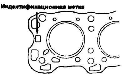
Note: Do not apply sealant to this surface.
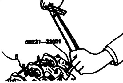
9. Using a special tool (09221-32001) and a torque wrench, tighten the cylinder head bolts in the sequence shown in the figure.
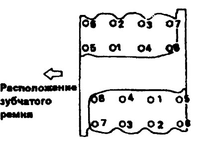
10. When tightening the head bolts, repeat tightening 2 or 3 times in succession, increasing the tightening torque each time until the required torque is achieved.
- Tightening torque: Cylinder head mounting bolts Cold engine (engine coolant temperature about 20°C) — 105-115 Nm.