
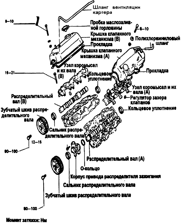
Removal
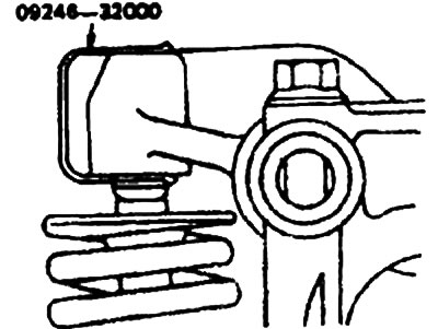
1. Before removing the rocker arm assembly and their shafts, install special devices (09246- to prevent the valve clearance adjusters from falling out.
Note: To prevent errors during subsequent installation, keep the rocker arms and valve lash adjusters in an order that clearly separates them between intake and exhaust.
Valve clearance adjuster
1. Check the ease of movement of the automatic slack adjuster by inserting a thin wire through the air outlet hole in the rocker arm and lightly pressing on the slack adjuster ball.
2. While holding the ball down, move the rocker arm up and down to check for ease of movement. If there is no movement, replace the automatic lash adjuster.
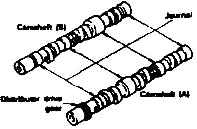
Camshaft
1. Replace the camshaft if the following areas are significantly worn or damaged.
- 1) Necks.
- 2) Working projections of cams.
- 3) Teeth of the ignition distributor drive gear.
- 4) Surface in contact with the seal.
2. If the camshaft bearings are significantly worn, replace the cylinder head.
3. If the oil seal lip is worn, replace it.
Height of cams
- Nominal - 41.15-41.35 mm
- Limit - 40.65 mm
Installation
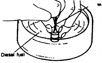
1. Adjust the automatic valve clearance adjuster in clean diesel fuel.
2. Using a thin wire, press the ball down slightly, then move the plunger up and down 4 or 5 times to release the air.
3. After applying engine oil to the camshaft journals and cams, install it into the cylinder head.
4. Insert the valve clearance adjusters, being careful not to spill the diesel fuel inside them. Then use a special tool to prevent them from falling out during installation.
The text is taken from an online source: HyundaiBook
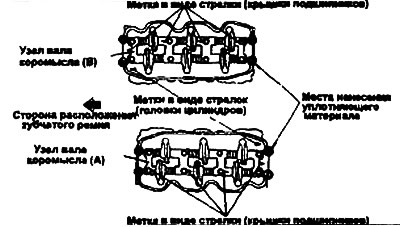
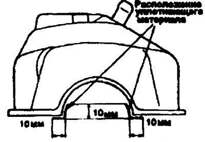
5. Apply a minimum amount of sealant in 4 places (see figure).
Note: The sealing material must not come into contact with the cylinder head surfaces that contact the camshaft journals.
- Sealing material - Threebond No.1324 or equivalent
6. Install the rocker arm shafts (A) and (B) so that the marks on the bearing caps are facing in the same direction as the similar mark on the cylinder head.
Note: The arrow marks on the rocker shafts (A) and (B) point towards each other.
7. Tighten the bearing cap bolts to the specified torque. Remove the special tools installed on the valve clearance adjuster.
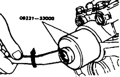
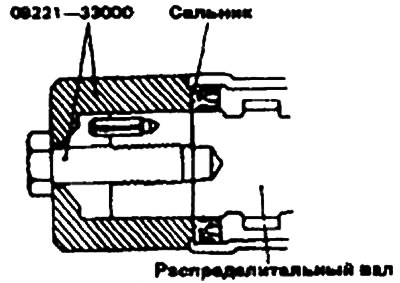
8. Apply a small amount of oil to the surface of the camshaft that contacts the lip of the oil seal. Using a special tool (09221-33000) install the seal.
 |
 |
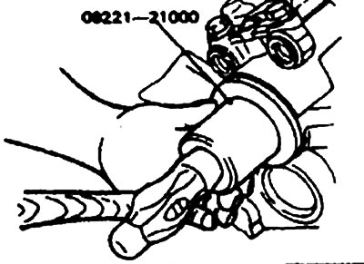
9. Using a special tool (09221-21000), install the O-ring.
10. After installing the valve cover, apply sealing material to the O-ring and to the top surface of the cylinder head.
- Sealing Material: Valve Cover - Threebond #1212D or equivalent
Note: Make sure the valve cover bolts are tightened to the specified torque. Overtightening the bolts will distort the cover, which may cause oil leakage.
- Tightening torque: Valve cover bolt - 8-10 Nm.
11. Using special tools (09231 -33200, 09231-33300), tighten the camshaft timing pulley bolt to the specified torque.
- Tightening torque: Camshaft timing pulley bolt - 80-100 Nm.