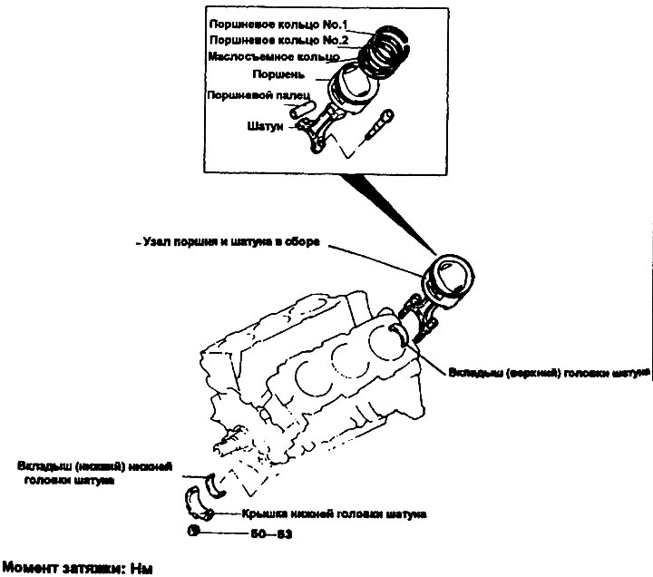
Removal
Connecting rod lower head cover
Warning: To avoid errors during subsequent assembly, arrange the bearings in accordance with their connecting rods (in the order of cylinder numbering).
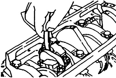
1. Unscrew the connecting rod caps, then remove the cap, as well as the upper and lower bearing shells.
2. Move the pistons with connecting rods to the tops of the cylinders.
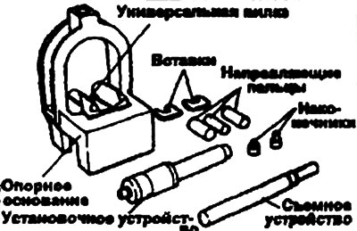
The procedure for removing and installing the piston pin
1. Use a special tool to separate and connect the piston and connecting rod (09234—33001).
2. Install the appropriate insert into the fork of the device. Position the insert between the connecting rod and the piston.
3. Insert the appropriate removal device into the opening of the fixture arch.
 |
 |
Caution: Center the piston, connecting rod and piston pin on the puller mandrel.
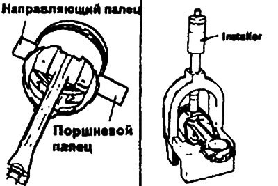
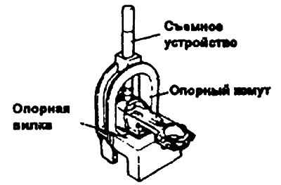
4. Press the piston pin out of the upper connecting rod head.
5. Install the appropriate guide pin into the piston and connecting rod small end. Insert the guide pin into the piston bore by hand. Push the piston pin out the other side of the piston.
Warning: The guide pin centers the connecting rod in the piston. When the piston, connecting rod, piston pin and guide pin are installed on the jig yoke, the guide pin centers the entire assembly. If too small a guide pin is used, the piston assembly will not be centered in the jig, which may result in damage to the jig yoke or insert.
6. Install the piston assembly onto the fork of the tool. The tool will support the connecting rod on the piston pin. Make sure the piston assembly slides on the fork until the guide pin contacts the insert.
7. Adjust the installation mandrel to the appropriate length by rotating the numbered sleeve on the lettered shaft until the alphanumeric value specified in the application diagram is obtained. Turn the knurled nut to lock the numbered sleeve on the shaft.
8. Insert the installation mandrel into the hole in the arc of the fixture. Press the piston pin into the connecting rod head until the bushing of the installation mandrel touches the top of the arc of the fixture.
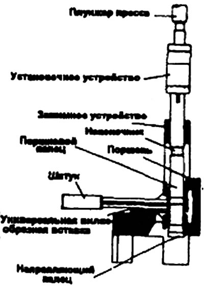
Warning: Do not apply a load greater than 2200 kgf when pressing the mounting mandrel sleeve into the arc.
Examination
Pistons and piston pins
1. Check each piston for scuffs, scoring, wear and other defects. Replace defective pistons.
2. Check each piston ring for breakage, damage, and excessive wear. Replace any defective rings. When replacing a piston, its rings are also replaced.
3. Check the fit of the piston pin in the piston boss holes. Replace defective pistons and piston pins. The piston pin should fit smoothly into the piston boss holes by hand at room temperature.
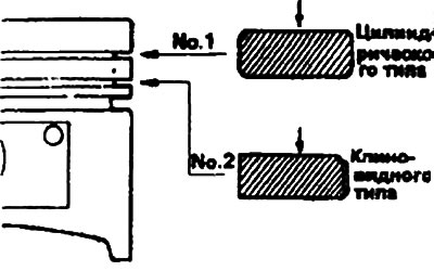
Piston rings
1. Check the side clearance of the piston rings. If the measured value exceeds the permissible value, insert a new ring into the piston groove and measure the side clearance. If the clearance still exceeds the permissible value, replace the piston and piston rings. If in this case the clearance does not exceed the permissible value, replace only the piston rings.
Piston ring lateral clearance:
- No. 1 - 0.03-0.09 mm
- No. 2 — 0.02-0.06 mm
Limit value:
- No. 1 - 0.1 mm
- No. 2 - 0.1 mm
2. To measure the gap in the piston ring lock, insert the ring into the cylinder. Set the ring in a plane perpendicular to the cylinder wall, pressing it lightly with the piston. Measure the gap with a plate feeler gauge. If the gap exceeds the permissible limits, replace the piston ring.
Piston ring gap:
- Nominal value:
- No. 1 — 0.30—0.45 mm
- No. 2 — 0.25—0.40 mm
- Oil scraper ring - 0.30-0.90 mm
- Limit value:
- No. 1, No.2 - 0.8 mm
- Oil scraper ring - 1.0 mm
When replacing piston rings without reboring the cylinders, place the ring in the lower, less worn part of the cylinder to check the clearance.
When replacing rings, make sure they are the same size.
Piston ring repair size and marking:
- 0.25 mm OS - 25
- 0.50 mm OS - 50
- 0.75 mm OS - 75
- 1,00 O.S — 100
Note: The marking is applied on the top side of the ring near the clasp.
Connecting rods
1. When installing the connecting rod cap, make sure that the cylinder numbers on the connecting rod and cap match. When installing a new connecting rod, make sure that the bearing retaining cutouts are on the same side.
2. Replace the connecting rod if there is damage to the pressure-bearing surfaces of the upper and lower heads, or if there is stepped wear or if the inner surface of the upper head bore is highly rough.
Installation
1. Install the spacer ring.
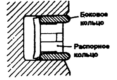
2. Install the upper side ring. To install it, insert one end of it between the wall of the piston ring groove and the spacer rubber ring, press it to the bottom of the groove and, pressing with your finger as shown in the figure, insert the ring into the groove.
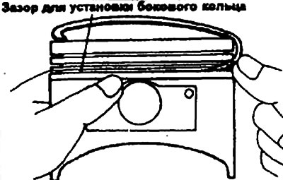
Warning: Do not use a piston ring expander when installing the side rings.
3. Install the lower side ring in the same way.
4. Apply motor oil to the surfaces
5. Using a piston ring expander, install piston ring No.2.
6. Install piston ring No.1.
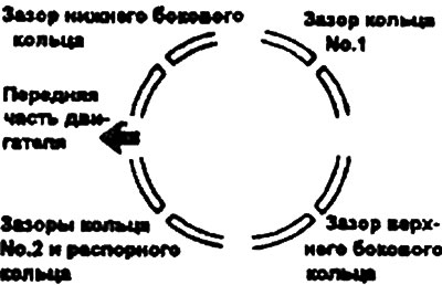
7. Position the piston rings so that the gaps in the joints of adjacent piston rings are as far apart as possible. Make sure that these gaps are not located in the plane of the piston pin and load bearing.
8. When installing the piston into the cylinder, press the rings into the piston grooves using a crimper.
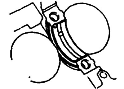
9. Install the main bearing shells into the cylinder block.
10. Install the lower bearing shells into the main bearing caps.
Note: Bearings with lubrication holes are installed in the cylinder block.
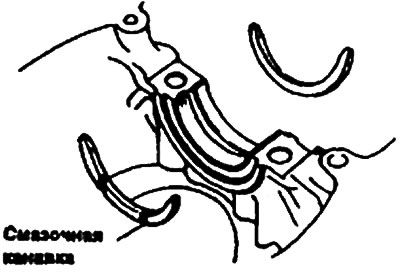
11. Install the axial load plates into the main bearing cap N9 3 so that the oil grooves face outward.
12. Make sure that the mark marking the front of the piston and the mark marking the front of the connecting rod (identification mark) are facing toward the front of the engine.
13. When installing the connecting rod lower head cover, make sure that the marks corresponding to the cylinder number on the connecting rod and cover match.
14. When installing the big end cap, make sure that the cutouts for retaining the bearing shells are located on the same side.
15. Tighten the connecting rod lower head cap nuts.
- Tightening torques: Lower head cover nuts - 50-53 Nm.
16. Check the bearing clearances, for which:
- 1) Remove oil and dirt from bearings and journals.
- 2) Cut a piece of plastic template the same length as the width of the bearing and place it along the journal axis away from the lubrication holes.
- 3) Install the bearing shells and cover. Tighten them to the specified torque. Do not rotate the crankshaft while performing this operation.
- 4) Remove the bearing cap and, using the scale printed on the template packaging, measure the thickness of the plastic template at its widest point.
Connecting rod lower head cover:
- Bearing clearance:
- Nominal - 0.016-0.046 mm
- Limit - 0.1 mm
17. Check the connecting rod side clearance.
- Lateral clearance - 0.10-0.25 mm
- Limit value - 0.4 mm