
Contents: Removal ⇓ Examination ⇓ Camshaft cam height ⇓ Checking the camshaft seal ⇓ Checking hydraulic compensators ⇓ Checking the timing chain ⇓ Installation ⇓
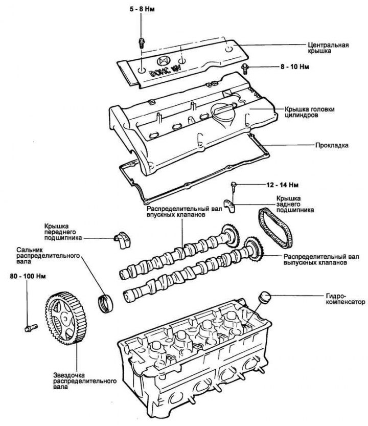
Fig. 2.41. Camshafts of a 1.6 L engine
The camshafts of the 1.6 L engine are shown in Fig. 2.41.
Removal
Disconnect the positive crankcase ventilation valve hose and vent hose.
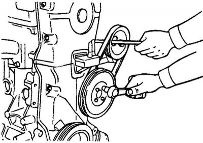
Fig. 2.42. Removing the coolant pump pulleys and crankshaft
Remove the coolant pump pulley and the crankshaft pulley (Fig. 2.42).
Remove the timing belt cover.
Loosen the timing belt tensioner pulley bolts, loosen the belt tension and temporarily secure the tensioner pulley.
Remove the timing belt from the camshaft sprocket.
Loosen the bolts securing the center cover and then remove the cover.
Remove the ignition coils as an assembly.
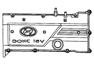
Fig. 2.43. Cylinder head cover
Loosen the cylinder head cover mounting bolts and then remove the cover (Fig. 2.43).
Remove the camshaft sprocket.
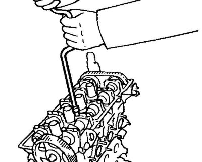
Fig. 2.44. Removing the camshaft bearing caps
(The text is provided by the web resource: «www.hyundaibook.ru»)
Remove the camshaft bearing caps and timing chain (Fig. 2.44).
Remove the camshafts.
Remove the hydraulic lifters.
Examination
Check the camshaft journals for wear. If the journals are significantly worn, replace the camshaft.
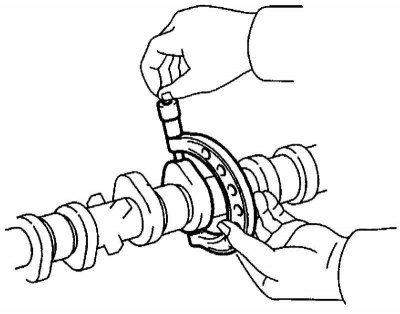
Fig. 2.45. Checking the protruding part of the camshaft cams
Check the protruding portion of the camshaft lobes for damage. If the camshaft lobes are damaged or their wear exceeds the permissible value, replace the camshaft (Fig. 2.45).
Camshaft cam height
Nominal value:
- intake: 43.4484 mm;
- outlet: 43.8489 mm.
Maximum permissible value:
- intake: 42.9484 mm;
- outlet: 43.3489 mm.
Inspect the camshaft lobes rear surface for damage or significant wear and replace if necessary.
Check the condition of the camshaft bed for any damage. If the camshaft bed is worn beyond the permissible limit, replace the cylinder head assembly or camshaft bearing covers.
- Axial clearance of the camshaft: 0.10–0.15 mm
Checking the camshaft seal
Check the seal lip for wear. If the lip is worn, replace the seal.
Check the condition of the camshaft surface that contacts the seal lip. If the surface is worn, replace the camshaft.
Checking hydraulic compensators
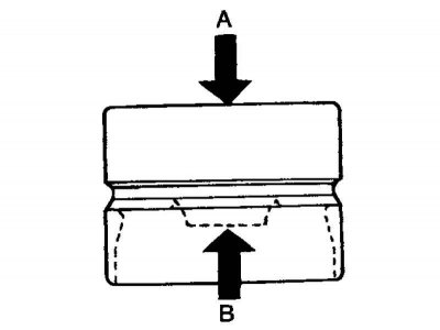
Fig. 2.46. Hydraulic compensator testing diagram
Fix the surface "A" of the hydraulic compensator filled with engine oil and press the stop "B" of the hydraulic compensator by hand. If the stop "B" moves, replace the hydraulic compensator (Fig. 2.46).
Other typical faults of the hydraulic compensator are listed in table 2.6.
Checking the timing chain
Check the chain components (bushings and plates) for wear. Replace the chain if wear is excessive.
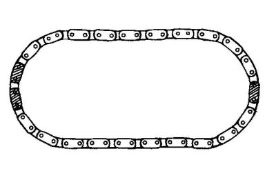
Fig. 2.47. Timing chain
Installation
Install the hydraulic lifters back into place.
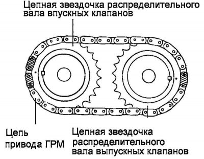
Fig. 2.48. Alignment of the timing chain with the chain sprockets of the intake and exhaust camshafts
Align the timing chain with the intake and exhaust camshaft sprockets as shown in Figure 2.48.
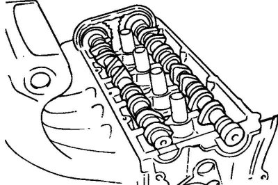
Fig. 2.49. Installing camshafts
Lubricate the camshaft bearing journals with engine oil, then install the camshaft in place (Fig. 2.49).

Fig. 2.50. Identification marks on bearing caps
Install the camshaft bearing caps. The identification marks on the bearing caps are intended to identify the installation location of the cap (inlet/outlet valve side) (Fig. 2.50).
- I: Intake camshaft.
- E: exhaust camshaft.
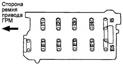
Fig. 2.51. The order of tightening the bolts securing the camshaft bearing caps
Tighten the camshaft bearing cap mounting bolts to the specified tightening torque in two or three steps in the order indicated by the numbers in Figure 2.51.
Tightening torque of the camshaft bearing cover bolts: 12–14 N·m.
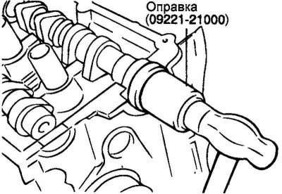
Fig. 2.52. Pressing in the camshaft seal using a special tool
Using a special tool (mandrel for installing camshaft seal 09221-21000), press in the camshaft seal (Fig. 2.52).
Make sure the camshaft oil seal lip is lubricated with engine oil. Position the seal on the camshaft from the timing belt sprocket side, then tap the seal with a hammer on the mandrel until it is flush with the surface.
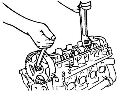
Fig. 2.53. Installing the camshaft sprocket
Install the sprocket (for the belt) of the camshaft and tighten its mounting bolt to the nominal tightening torque (Fig. 2.53).
Tightening torque of the camshaft sprocket mounting bolt (for belt): 80–100 N·m.
Align the marks on the crankshaft and camshaft sprockets with the corresponding timing marks and set the piston of cylinder No.1 to TDC of the compression stroke.
Install the cylinder head cover.
Tightening torque of cylinder head cover bolts: 8–10 Nm.
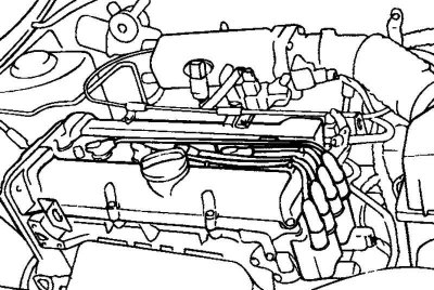
Fig. 2.54. Installing the central cover
Install the ignition coil assemblies, spark plug wires and center cap (Fig. 2.54).
Install the timing belt, and then when the tensioner pulley tensions the belt, tighten the tensioner fastener.
Install the timing belt covers.
Tightening torque of timing belt cover mounting bolts: 8–10 N·m.
Install the coolant pump pulley and crankshaft pulley.