


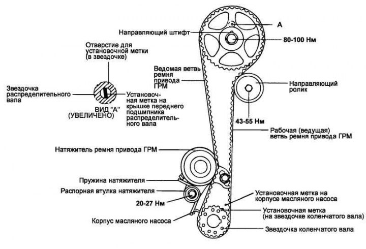
Fig. 2.55. Timing Belt Components
Removal
Loosen the coolant pump pulley mounting bolts.
Loosen the generator mounting bolt.
Remove the coolant pump pulley and alternator drive belt.
Remove the crankshaft pulley.
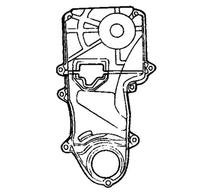
Fig. 2.56. Timing belt cover
Remove the timing belt cover (Fig. 2.56).
Move the tensioner toward the coolant pump and temporarily tighten the mounting bolts to prevent the tensioner from returning.
Loosen the camshaft sprocket mounting bolt.
Remove the camshaft sprocket.
Remove the timing belt.
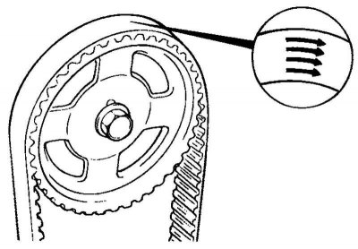
Fig. 2.57. Marks indicating the direction of rotation
Note: If the timing belt is reused, it is necessary to mark with chalk on the reverse (non-working) surface of the belt an arrow indicating the direction of rotation (or the location of the crankshaft pulley) so as not to confuse the direction of its rotation when installing the belt (Fig. 2.57).
Loosen the crankshaft sprocket mounting bolts. Remove the sprocket and guide washer from the crankshaft.
Remove the timing belt tensioner.
Checking the sprocket, timing belt tensioner roller and guide roller
Check the camshaft sprocket, crankshaft sprocket, timing belt tensioner pulley and idler pulley for excessive wear, cracks or damage.
Replace them if necessary.
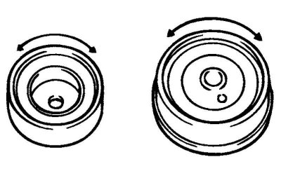
Fig. 2.58. Checking the smooth rotation of the timing belt tensioner roller
Check the ease and smoothness of rotation of the timing belt tensioner roller and guide roller and make sure there is no excessive play or extraneous noise during rotation (Fig. 2.58).
Replace the roller if necessary.
Replace the roller if you find signs of grease leaking from its bearing.
Check the belt for dirt or oil deposits. Replace the belt if necessary. Minor dirt on the belt can be removed with a dry cloth or cleaning paper. Do not use solvents for this purpose.
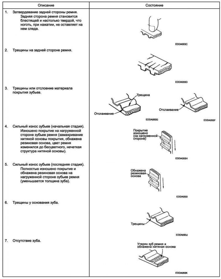
Fig. 2.59. Timing belt defects
When overhauling the engine or adjusting the belt tension, carefully inspect the belt. If any of the following defects are found, replace the belt with a new one (Fig. 2.59).
Note: A normal belt should have clearly pointed sidewalls, similar to knife-cut surfaces.
Installation
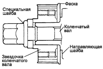
Fig. 2.60. Installing the guide washer and crankshaft sprocket
Install the guide washer and crankshaft sprocket as shown in the figure (Fig. 2.60).
Please pay attention to the orientation of the parts during installation.
Tightening torque of the crankshaft sprocket mounting bolt: 140–150 N·m.
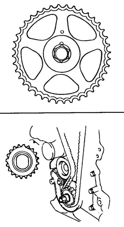
Fig. 2.61. Installing the camshaft sprocket
Install the camshaft sprocket and tighten its mounting bolt to the specified torque (Fig. 2.61).
Tightening torque of the camshaft sprocket mounting bolt: 80–100 N·m.
Install the guide roller and tighten its mounting bolt to the specified torque.
Tightening torque of the guide roller mounting bolt: 43–55 N·m.
Align the crankshaft and camshaft sprocket marks with the timing marks when the piston of cylinder No.1 is at TDC of the compression stroke.
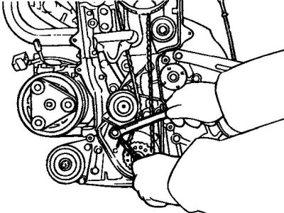
Fig. 2.62. Securing the lower end of the spring
Install the timing belt tensioner components in the following order: tensioner, spring, and tensioner spacer sleeve. Temporarily tighten the tensioner pivot bolt. Temporarily tighten the tensioner adjusting bolt with washer (in the longitudinal hole of the tensioner bracket). Hook the lower end of the spring onto the protrusion on the oil pump housing, as shown in the figure (Fig. 2.62).
Move the tensioner pulley towards the coolant pump, temporarily tighten the tensioner mounting bolts.
Place the timing belt on the crankshaft sprocket.

Fig. 2.63. Tensioning the working branch of the belt
Place the timing belt on the camshaft sprocket. After this, make sure that the working branch of the belt is tensioned. Then apply force in the opposite direction of rotation (counterclockwise) to the camshaft sprocket to tighten the working branch of the belt, and make sure that all the timing marks are aligned (Fig. 2.63).
Tighten the tensioner adjusting bolt first, then the tensioner pivot bolt.
Tightening torque of the tensioner mounting bolt: 20–27 N·m.
Turn the crankshaft one revolution in the normal direction of rotation (clockwise) and again align the crankshaft mark with the timing mark (cylinder No.1 at TDC of the compression stroke).
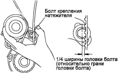
Fig. 2.64. Checking the timing belt tension
Check the timing belt tension again. Use your hand to secure the tensioner and timing belt together, then apply light horizontal pressure with your thumb (approximately 49 N) on the belt opposite the center of the tensioner pulley (Fig. 2.64).
Make sure the top of the timing belt tooth is offset by approximately 1/4 the width of the tensioner adjusting bolt head (relative to the flat of the bolt head).
Install the timing belt cover.
Tightening torque of timing belt cover mounting bolts: 8–10 N·m.
Install the crankshaft pulley. Make sure the crankshaft sprocket guide pin fits into the small hole in the crankshaft pulley.
Tightening torque of the crankshaft pulley mounting bolts: 140–150 N·m.
Install the coolant pump pulley.
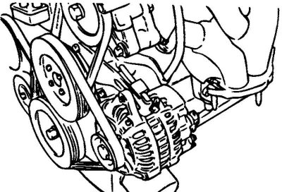
Fig. 2.65. Generator drive belt
Install the generator drive belt and adjust its tension (Fig. 2.65).