
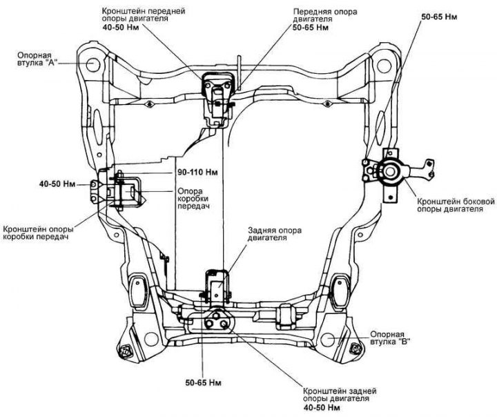
Fig. 2.23. Fastening the power unit of a 1.6 l engine.
Removal
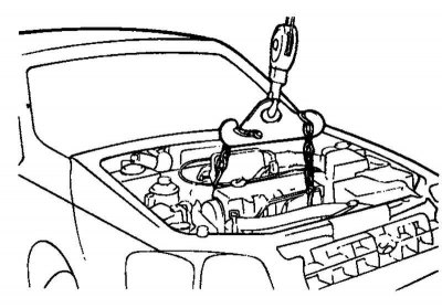
Fig. 2.24. Fastening the engine to the crossmember
Secure the engine to the crossbar using the mounting brackets and hang it on the lift, then slightly lift the engine assembly to relieve the supports from the weight of the power unit (Fig. 2.24).
Unscrew the bolts securing the side engine support (to the engine and body).
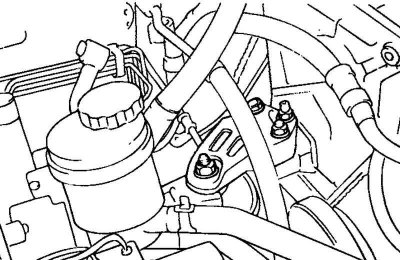
Fig. 2.25. Lateral engine support
Remove the side support (assembled with the bracket) from the engine (Fig. 2.25).
On models with a 5-speed manual transmission, remove the reverse light switch sensor.
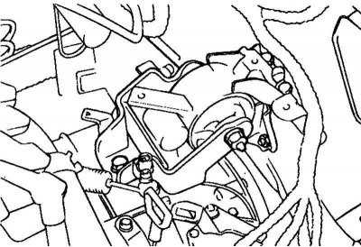
Fig. 2.26. Gearbox support mounting bolt
Loosen the gearbox support mounting bolt (to the gearbox support bracket) (Fig. 2.26).
Remove the plugs from inside the left wing splash shield. Remove the bolts securing the gearbox support bracket to the subframe.
Remove the transmission support assembly.
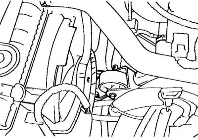
Fig. 2.27. Front engine mount
Remove the front engine mount assembly from the subframe (Fig. 2.27).
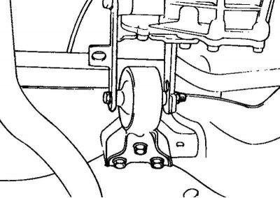
Fig. 2.28. Rear engine mount
Remove the rear engine mount assembly from the subframe (Fig. 2.28).
Installation
To prevent the support stop from moving, make sure it is properly inserted into the support inner tube.
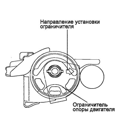
Fig. 2.29. Support limiter installation diagram
Install the support limiter in place, making sure that it is positioned correctly (Fig. 2.29).
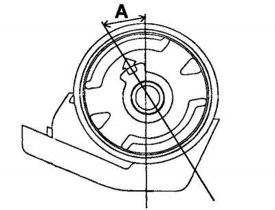
Fig. 2.30. Installing the front engine mount
Position the engine support so that it is at the correct angle (A) to the bracket (Fig. 2.30).
- Models with automatic transmission: 27–33°.
- Models with manual transmission: 11–17°.
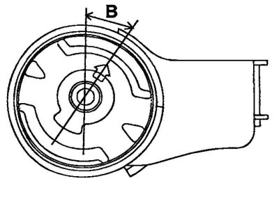
Fig. 2.31. Installing the rear engine support
Position the engine support so that it is at the correct angle (B) to the bracket (Fig. 2.31).
- Models with automatic transmission: 30–36°.
- Models with manual transmission: 17–23°.
Installing the subframe support bushing
Note: The front and rear cross member support bushings of the subframe are guides.
Note: Make sure the support bushings are oriented correctly when installing.
Note: There are markings (in the form of arrows) indicating the installation direction in two places on the upper surface of the subframe cross members and the corresponding support bushings.
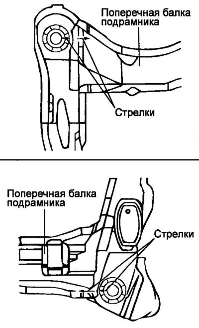
Fig. 2.32. Installing support bushings into the inner tubes of the subframe cross beams
When installing the support bushings into the inner tubes of the subframe cross members, align the direction of the arrow on the bushing with the direction of the arrow on the subframe cross member (Fig. 2.32).
Note: Before installation, check that the arrow on the support sleeve is parallel to the arrow on the subframe crossmember. Make sure that the direction of the arrow on the installed support sleeve deviates no more than ±3° from the direction of the arrow on the subframe crossmember.