
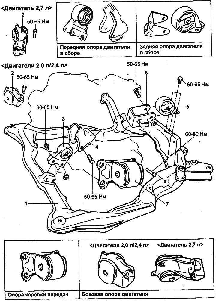
Powertrain mounts and subframe.
1 - subframe, 2 - side engine support, 3 - front engine support, 4 - front engine support bracket, 5 - rear engine support, 6 - rear engine support bracket, 7 - gearbox support assembly with bracket.
Removal and installation
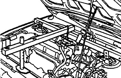
Secure the engine to the crossmember using the mounting brackets and hang it on the lift, then slightly lift the engine assembly to relieve the supports from the weight of the power unit.
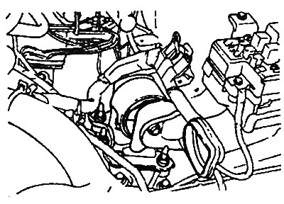
Side engine mount
1. Unscrew the bolts securing the side engine support (to the engine and body).
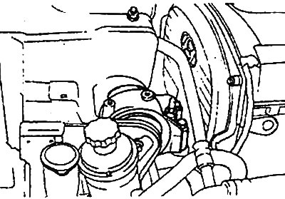
Engines 2.0L/2.4L |
Engine 2.7 l |
2. Remove the side engine support.
3. Installation is carried out in the reverse order of removal.
Tightening torque:
- bolts securing the side support to the support bracket: 90-100 Nm
- support mounting bolt: 50-65 Nm
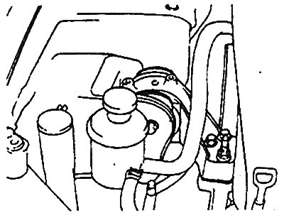
Transmission support
1. Unscrew the gearbox support mounting bolt (to the gearbox support bracket).
Engines 2.0L/2.4L |
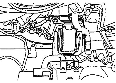
Engine 2.7 l. |
2. Loosen the bolts securing the support to the subframe, then remove the gearbox support.
3. Installation is carried out in the reverse order of removal.
Tightening torque:
- gearbox support mounting bolt to support bracket: 90-100 Nm
- support mounting bolt: 60-80 Nm
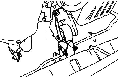
Front engine mount
1. Loosen the front engine mount mounting bolt (to the support bracket).
2. Loosen the mounting bolts and remove the front engine mount from the subframe.
3. Installation is carried out in the reverse order of removal.
Tightening torque:
- Front engine mount to support bracket bolt: 50-65 Nm
- Support mounting bolt: 60-80 Nm
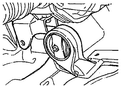
Rear engine mount
1. Loosen the rear engine mount mounting bolt (to the support bracket).
2. Loosen the mounting bolts and remove the rear engine mount from the subframe.
3. Installation is carried out in the reverse order of removal.
Tightening torque:
- Rear engine mount to support bracket bolt: 50-65 Nm
- Support mounting bolt: 50-65 Nm
Subframe support bushings
Note:
- The front cross member support bushings of the subframe are guides.
- Make sure the support bushings are oriented correctly when installing.
1. Remove the subframe (see chapter "Engine - mechanical part").
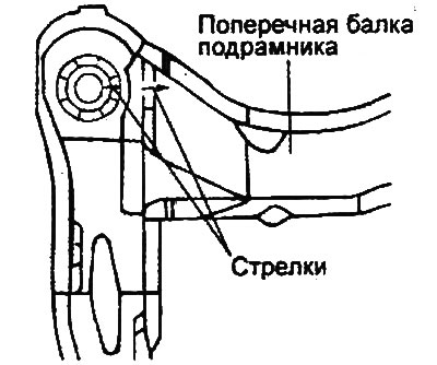
2. In two places on the upper surface of the subframe cross beams and the upper surface of the corresponding support bushings there are marks (in the form of arrows) indicating the installation direction.
3. When installing the support bushings into the inner tubes of the front subframe cross member, align the direction of the arrow on the bushing with the direction of the arrow on the subframe cross member.
Note: Before installation, check that the arrow on the support sleeve is parallel to the arrow on the subframe crossmember. Make sure that the direction of the arrow on the installed support sleeve deviates no more than ±3 degrees from the direction of the arrow on the subframe crossmember.
4. The subframe is installed in the reverse order of removal.