
Disassembly
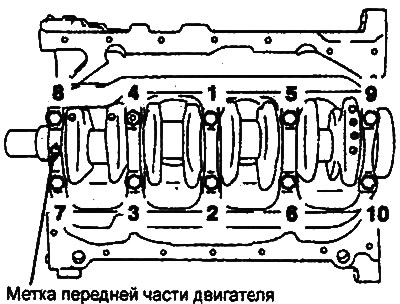
When removing parts, refer to the figure "Crankshaft, flywheel and torque converter drive plate".
Note: To simplify installation, arrange the removed parts (connecting rod caps, connecting rod and main bearing shells) in the order in which they correspond to cylinder numbers and installation direction.
Examination
Crankshaft
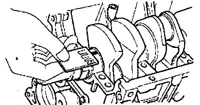
1. Check the crankshaft main and connecting rod journals for damage (scoring and seizure), excessive wear and cracks. Also check the oil passage holes for blockage. Repair or replace the faulty part.
2. Check the taper and out-of-roundness of the main and connecting rod journals of the crankshaft.
- Nominal value:
- 2.0L/2.4L Engines:
- Main journal diameter: 56.982-57.000 mm
- Crankpin diameter: 44.980-45.000 mm
- Taper and out-of-roundness of main and connecting rod journals: 0.003 mm or less
- 2.7L Engine:
- Main journal diameter: 61.982-62.000 mm
- Crankpin diameter: 47.982-48.000 mm
- Ovality of connecting rod and main journals: no more than 0.003 mm
- Taper of connecting rod and main journals: no more than 0.005 mm
- Maximum permissible value: 0.1 mm
 |
Engine 2.7 l. |
Measuring the clearance in a connecting rod bearing using a plastic gauge
Note: Using this method significantly simplifies the procedure for determining clearances in crankshaft bearings.
1. Check that the alignment marks on the connecting rod and connecting rod cap are in line (to ensure correct assembly).
2. Unscrew the connecting rod cover fastening nuts.
3. Remove the connecting rod cap and one of the connecting rod bearing shells.
4. Clean the crankshaft journals and bearings from oil and dirt.
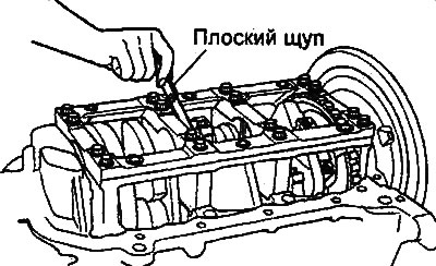
5. Cut a piece of plastic gauge to a length equal to the width of the bearing shell and place it parallel to the axis of the journal away from the oil passage hole.
6. Install the bearing shell and connecting rod cap and tighten the nuts to the specified torque.
Caution: Do not rotate the crankshaft during this procedure.
7. Remove the connecting rod cover and use the scale printed on the gauge packaging to determine the bearing clearance.
Nominal value:
- 2.0L/2.4L engines: 0.015-0.048 mm
- Engine 2.7L: 0.018-0.036 mm
- Maximum permissible value: 0.1 mm
The article is borrowed from an online resource: hyundaibook.ru
Engines 2.0 l / 2.4 l.
Note:
- Do not machine the bearing or connecting rod cap to adjust clearance.
- If it is not possible to adjust the clearance to the nominal value using the liners, replace the crankshaft and liners with new ones.
Determining the clearance value in the main bearing of the crankshaft using the plastic gauge method
Note: Using this method significantly simplifies the procedure for determining clearances in crankshaft bearings.
1. Clean the cylinder block surfaces and main bearing caps, crankshaft main journals and bearing shells from oil deposits, grease and other contaminants.
2. Carefully place the crankshaft into the cylinder block.
3. Cut a piece of calibrated plastic wire the same length as the journal width, then place it on the crankshaft journal along the crankshaft axis.
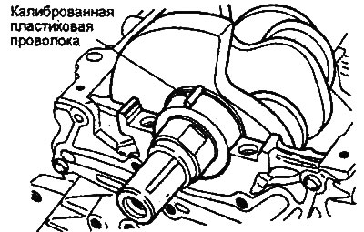
4. Carefully install the crankshaft bed (2.0L/2.4L engines) or bearing caps (2.7L engine) and tighten the mounting bolts to the specified tightening torque.
Caution: Do not rotate the crankshaft during this procedure.
Tightening torque:
- 2.7L Engine:
- M8 (bolts No.9-6): 10-12 Nm
- M10 (bolts #1-8): 14-16 Nm
- Engines 2.0l/2.4l: 25 Nm + 90°
5. Loosen the mounting bolts and carefully remove the cover.
6. Measure the width of the crushed plastic gauge wire at its widest point using the scale printed on the plastic gauge package.
- Engines 2.0L/2.4L:
- Main bearing clearance:
- Nominal value:
- No. 1, 2, 4, 5: 0.018-0.036 mm
- No.3: 0.024-0.042 mm
- Maximum permissible value: No.1, 2, 4, 5: 0.1 mm
- 2.7L Engine:
- Main bearing clearance:
- Nominal value: 0.004-0.022 mm
- Maximum permissible value: 0.1 mm
Note:
- Do not machine the bearing or bearing cap to adjust clearance.
- If it is not possible to adjust the clearance to the nominal value using the liners, replace the crankshaft and liners with new ones.
Crankshaft oil seals
Check the front and rear crankshaft oil seals for damage or wear on the working edges. Replace the defective oil seal.
Crankshaft bed (2.0L/2.4L engines)
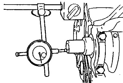
After installing the crankshaft bed (main bearing caps), check that the crankshaft rotates smoothly and the crankshaft axial clearance corresponds to the nominal value. If the axial clearance exceeds the maximum permissible value, replace the bearing thrust half rings and/or bearing shells.
- Nominal value: 0.05-0.25 mm
- Maximum permissible value: 0.40 mm
Assembly
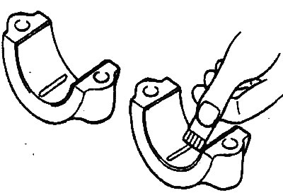
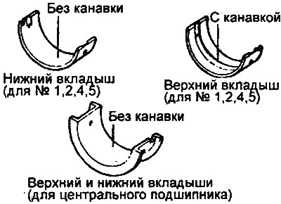
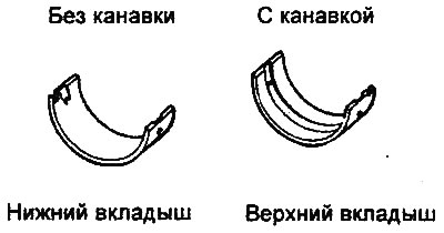
1. Install the upper main bearing shells (with oil groove) into the crankshaft bed on the cylinder block.
2. Install the lower bearing shells (without grooves) into the crankshaft bed (main bearing caps).
Engines 2.0 l / 2.4 l.
Note: (2.0L/2.4L engines) The crankshaft center bearing shells (combined with the thrust bearing) do not have oil grooves.
Engine 2.7 l.
3. Apply engine oil to the main and connecting rod journals of the crankshaft. Install the crankshaft.
4. Install the main bearing caps (crankshaft bed - 2.0L/2.4L engines) with the arrow mark facing the front of the engine.
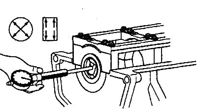
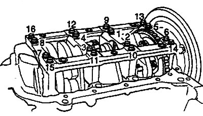
5. Tighten the main bearing cap bolts (2.7L engine) or crankshaft bed bolts (2.0L/2.4L engines) to the specified torque in the sequence shown in the corresponding illustration.
Note: The cover mounting bolts should be tightened gradually in four to five steps with increasing torque, then tightened to the nominal torque.
Tightening torque:
- 2.7L Engine:
- M7 (bolts No.9 - 16): 10-12 Nm
- M10 (bolts No.1 - 8): 14 -16 Nm
- 2.0L/2.4L engines: 25Nm + 90°
Engine 2.7 l. |
Engines 2.0 l / 2.4 l. |
6. Check the smooth rotation of the crankshaft and measure the axial clearance of the shaft.
- 2.7L Engine:
- Nominal value: 0.07-0.25 mm
- Maximum permissible value: 0.40 mm
- Engines 2.0 l / 2.4 p:
- Nominal value: 0.05-0.25 mm
- Maximum permissible value: 0.40 mm
Engines 2.7 l.
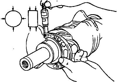
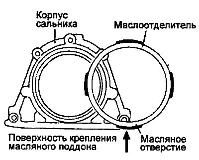
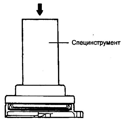
7. Using a special tool (crankshaft rear oil seal installation mandrel), install the crankshaft rear oil seal into the oil seal housing.
Attention:
- Installation of a previously used seal is not permitted.
- (2.0L/2.4L engines) Install the oil seal so that the hole (arrow in the illustration) of the oil separator faces downward (towards the oil pan).
Engines 2.0 l / 2.4 l. |
 |
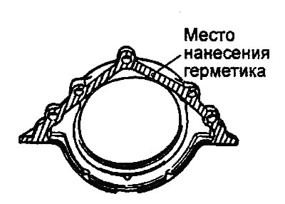
8. (2.7L Engine) Apply sealant to the oil seal housing at the locations shown in the figure. Install the oil seal housing onto the cylinder block and tighten the rear oil seal housing mounting bolts.
- Tightening torque: 10-12 Nm
9. (2.0L/2.4L Engines) Install the oil seal housing assembly onto the new gasket.
- Tightening torque: 10-12 Nm
10. (Except models with automatic transmission - 2.0L/2.4L engines) Install the rear plate of the cylinder block.
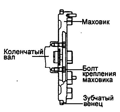
11. (Models with manual transmission) Install the flywheel assembly and tighten its mounting bolts to the specified torque.
Tightening torque:
- 2.0L/2.4L engines: 130-140 Nm
- 2.7L Engine: 73-77 Nm
Engine 2.7 l.
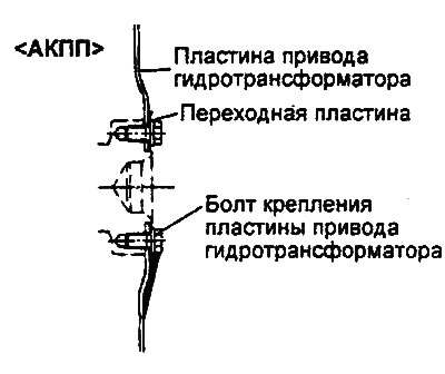
12. (Automatic transmission models, 2.0L / 2.4L engines) Install the crankshaft bushing and adapter plate to the cylinder block, then install the automatic transmission torque converter drive plate and tighten its mounting bolts to the specified torque.
- Tightening torque: 130-140 Nm
13. (Automatic transmission models, 2.7L engine) Install the adapter plate and the automatic transmission torque converter drive plate.
- Tightening torque: 73-77 Nm
Engine 2.7 l.