
Contents: Removal and disassembly ⇓ Examination ⇓ Repair (replacement of piston pin) ⇓ Assembly and installation ⇓
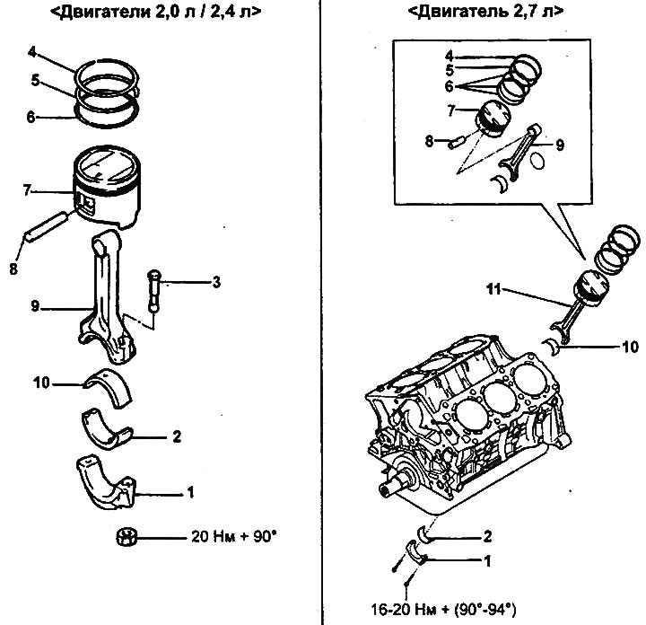
Piston and connecting rod.
1 - connecting rod cap, 2 - lower connecting rod bearing shell, 3 - bolt (2.0 l / 2.4 l engines), 4 - compression ring No.1, 5 - compression ring No.2, 6 - oil scraper ring, 7 - piston, 8 - piston pin, 9 - connecting rod, 10 - upper connecting rod bearing shell, 11 - piston and connecting rod assembly (2.7 l engine).
Note: (2.0L/2.4L engines) Tighten the connecting rod cap locknut to the yield point.
Removal and disassembly
Caution: Arrange the removed parts (connecting rods, connecting rod caps, connecting rod bearing shells) in the order they correspond to the cylinder numbers to ensure correct subsequent assembly.
When removing parts, refer to the drawing "Piston and connecting rod".
When removing parts, pay attention to the following operations.
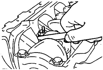
- a) Loosen the connecting rod cap mounting bolts, then remove the connecting rod cap and the lower connecting rod bearing shell.
- b) Push the piston and connecting rod assembly out of the cylinder block towards the cylinder head gasket surface.
Caution: Be careful when removing the piston with the connecting rod assembly, do not let the connecting rod touch the cylinder surface and the crankshaft journal.
- c) Apply the cylinder number to the side surface of the connecting rod to facilitate subsequent assembly.
Engines 2.0 l/2.4 l. |
Engines 2.7 l. |
Examination
Piston and piston pin
1. Check each piston for scratches, burrs, wear and other defects. Replace the piston if defects are found.
2. Check each piston ring for breaks, damage or significant wear. Replace any defective rings.
If it is necessary to replace the piston, its piston rings should be replaced at the same time.
3. Checking the piston pin.
- a) Try to insert the piston pin into the piston hole using your thumb. You should feel resistance. Replace the pin if it fits into the hole easily or if there is significant play. Replace the piston pin if there are any defects.
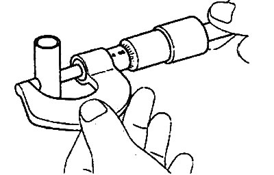
- b) Measure the piston pin diameter.
- Nominal value (2.0/2.4L engines): 22.00-22.01 mm
Piston rings
1. Measure the clearance between the piston ring and the piston groove. If the measured clearance exceeds the maximum permissible value, install a new piston ring and re-measure the clearance. If the measured clearance again exceeds the maximum permissible value,
permissible value, replace the piston and rings as an assembly. If the measured clearance is less than the maximum permissible value, replace only the piston rings.
Clearance between piston ring and piston groove:
- Nominal value:
- 2.0L/2.4L Engines:
- Compression rings: 0.02-0.06 mm
- Oil scraper ring: 0.06-0.15 mm
- 2.7L Engines:
- Compression ring #1: 0.04-0.08 mm
- Compression ring #2: 0.03-0.07 mm
- Maximum permissible value:
- Compression ring #1: 0.1mm
- Compression ring #2: 0.1mm
Piston ring groove width:
- 2.0L/2.4L Engines:
- Compression ring #1: 1.21-1.23 mm
- Compression ring #2: 1.51-1.53 mm
- Oil scraper ring: 2.81-2.83 mm
- 2.7L Engine:
- Compression ring #1: 1.23-1.25 mm
- Compression ring #2: 1.22-1.24 mm
- Oil scraper ring: 2.515-2.535 mm
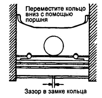
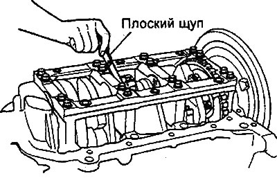
2. To measure the piston ring gap, install the piston ring into the cylinder bore.
Position the ring at a right angle to the cylinder wall generatrix, carefully moving it downwards with the piston. Measure the gap in the ring lock with a flat feeler gauge. If the measured gap exceeds the maximum permissible value, replace the piston ring.
Piston ring gap:
- Nominal value:
- 2.0L / 2.4L Engines:
- Compression ring #1: 0.25-0.35 mm
- Compression ring #2: 0.40-0.55 mm
- Oil scraper ring: 0.1-0.4 mm
- 2.7L Engine:
- Compression ring #1: 0.20-0.35 mm
- Compression ring #2: 0.37-0.52 mm
- Oil scraper ring (scrapers:) 0.20-0.70 mm
- Maximum permissible value:
- Compression rings #1 and #2: 0.8 mm
- Oil scraper ring: 1.0 mm
3. (2.7L engine) When replacing piston rings without boring the cylinders to the repair size, check the gap in the ring lock at a point located at the bottom of the cylinder (zone of least wear).
Piston ring size identification marks:
- Nominal size: No mark
- Repair size 0.25 mm: 25
- Repair size 0.50 mm: 50
Note: The repair size identification mark is located on the top of the piston ring near the ring joint.
Connecting rods
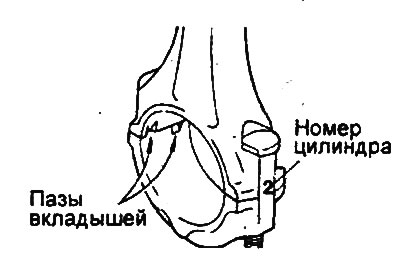
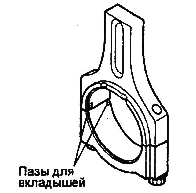
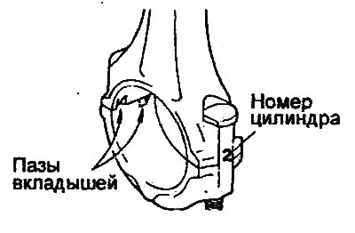
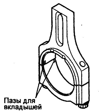
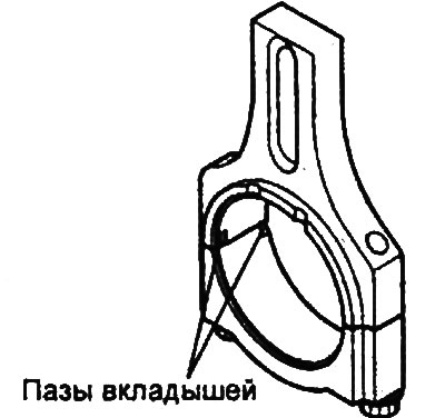
1. When installing the connecting rod cap, make sure that the cylinder number marks (made during disassembly) on the connecting rod and connecting rod cap match. When installing a new connecting rod, make sure that the locking grooves of the bearing shells in the connecting rod cap and connecting rod are located on the same side.
Engines 2.0 l/2.4 l. |
Engines 2.7 l. |
2. Replace the connecting rod if there is damage to the end surface of the upper or lower heads. If there is a bend or twisting of the connecting rod, or the surface of the hole for the piston pin in the upper head of the connecting rod is significantly worn, replace the connecting rod.
Nominal value:
- Twist: 0.1mm or less
- Bending: 0.05mm or less
Repair (replacement of piston pin)
1. Using special tools, disassemble and assemble the piston and connecting rod assembly.
2. The piston pin is pressed into the upper head of the connecting rod, and the piston slides along it at a certain temperature.
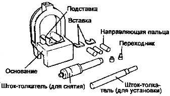
3. The set of special tools consists of a base with a stand and inserts, guides, adapters, a push rod for removal and a push rod for installation. When removing or installing the piston pin, the piston is held on the base of the device. The guide devices facilitate the positioning of the piston pin during its removal and installation, when the connecting rod rests on the inserts of the stand.
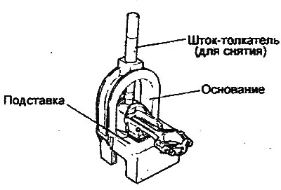
4. To remove the piston pin, place the piston on the base and position the connecting rod on the support insert. Insert the push rod (for removal) through the arc of the upper part of the base into the piston pin and remove the pin using a press.
5. When installing a new pin, it is necessary to install the corresponding support insert to support the connecting rod.
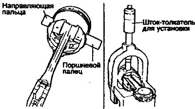
6. Position the small end of the connecting rod inside the piston. On one side of the piston, insert the appropriate guide through the piston and connecting rod, then push the guide down slightly by hand so that it is held by the piston. On the other side of the piston, insert the piston pin and place the piston and connecting rod together on the base of the tool with the pin guide facing down.
Note: The guide is necessary to center the connecting rod relative to the piston bosses. If the assembly is done correctly, the pin guide will be exactly centered in the arc hole of the top of the base and touching the support insert. If the wrong size pin guide is used, the piston (and connecting rod) and piston pin will not be aligned with the base hole.
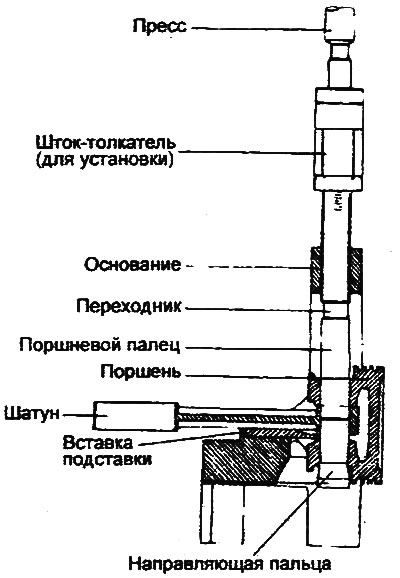
7. Insert the push rod (for installation) through the hole in the arc of the upper part of the base until it stops in the adapter on the piston pin and using a hydraulic press, drive the pin into the piston and the upper head of the connecting rod. Continue pressing until the moment when the guide of the pin falls from the bottom of the base and the push rod rests against the arc of the upper part of the base.
Caution: Do not exceed the maximum permissible force when pressing in the piston pin at the moment when the push rod rests against the arc of the upper part of the base.
- Maximum permissible force during pressing: 12500±5000 N
Assembly and installation
1. Install the oil scraper ring expander.
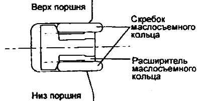
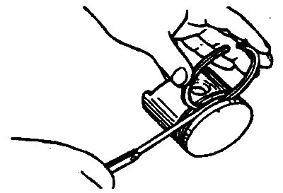
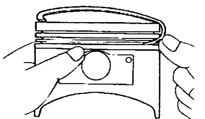
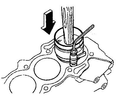
2. Install the upper oil scraper ring. To install the scraper, first place one end of the scraper between the expander and the piston groove, then hold the end of the scraper and press the scraper with your finger to insert it into the groove as shown in the figure.
Caution: Do not use a piston ring expander when installing oil ring scrapers.
3. Install the lower oil scraper ring according to the procedure given in step 2.
4. Apply engine oil to the piston and piston ring grooves all the way around.
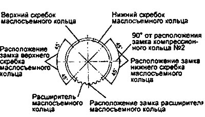
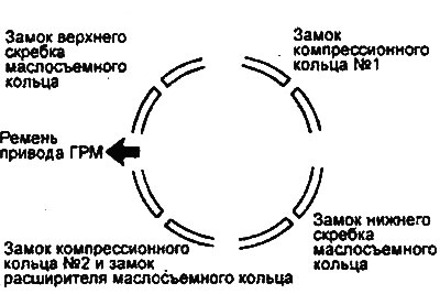
Note: Make sure the scraper and oil ring expander locks are positioned as shown in the illustration.
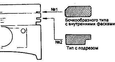
5. Using a piston ring expander, install compression ring #2.
6. Install compression ring No.1.
7. Position the ring joints as far apart as possible. Make sure that the joint of any ring is not on the piston pin axis or in a direction perpendicular to this axis.
8. Using a special device, securely fix the piston rings on the piston before installing the piston assembly into the cylinder.
9. Install the upper bearing shells into the connecting rods in the cylinder block.
10. Install the lower bearing shells into the connecting rod caps.
11. When installing, make sure that the "front" mark on the piston and the "front" identification mark on the connecting rod are facing the front of the engine (towards the timing belt).
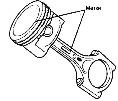
12. When installing the connecting rod cap, make sure that the cylinder number marks (made during disassembly) on the connecting rod and connecting rod cap match. When installing a new connecting rod, make sure that the locking grooves of the bearing shells in the connecting rod cap and connecting rod are located on the same side.
Engines 2.7 l.
13. When assembling, the connecting rod cap mounting bolts should be tightened as follows:
- a) Apply oil to the threads of the mounting nuts and the contact points of the connecting rod nuts and bolts.
- b) Tighten the nuts of the connecting rod cap bolts to the specified tightening torque.
Tightening torque:
- 2.0L/2.4 engines: 20 Nm + 90°
- 2.7L Engine: 16-20 Nm + (90°-94°)
Attention:
- Do not reinstall used (removed during disassembly) connecting rod cap bolts.
- When installing new connecting rod cap bolts, do not tighten them more than three times.
14. Check the side clearance between the lower head of the connecting rod and the corresponding web of the crankshaft.
- Nominal value: 0.10-0.25 mm
- Maximum permissible value: 0.40 mm
Engines 2.0 l / 2.4 l. |
Engine 2.7 l. |