
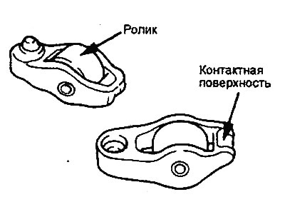
Checking the valve rocker arms
1. Check the surface of the valve rocker roller, replace the rocker arm if there is local wear, damage, or scoring;
2. Check the rotation of the roller and replace the valve rocker arm if it is jammed or has excessive play.
3. Check the condition of the rocker arm tappet surface (the point of contact with the end of the valve stem) for damage or scoring. Replace the rocker arm if significant wear is detected.
Checking the tightness and cleaning hydraulic compensators
Attention:.
- The hydraulic compensator is a precision part. Do not allow dust, dirt or other foreign particles to enter it.
- Do not disassemble the hydraulic compensator.
- When flushing the hydraulic compensator, use only clean diesel fuel.
1. Prepare three containers ("A", "B" and "C") with a sufficient amount of clean diesel fuel (approximately 5 liters) to completely immerse the hydraulic compensator, located vertically.
2. Place the hydraulic compensator in container "A" and clean it from the outside. If the deposits are difficult to remove, use a nylon brush.
3. Cleaning the internal cavities of the hydraulic compensator.
- a) Immerse the hydraulic compensator in container "B" as shown in the figure.
- b) Lightly pressing down the steel inner ball of the hydraulic compensator with a special rod, simultaneously move the plunger up and down (5-10 times) until the plunger begins to move smoothly. This will eliminate the plunger hanging and remove contaminated oil.
Note: The steel ball spring is weak, so the performance of the hydraulic compensator may be impaired if strong pressure is applied to the rod when removing air.
Note: If the plunger remains stationary or another malfunction of the mechanism is detected, replace the hydraulic compensator.
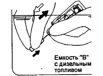
- c) Remove the hydraulic compensator from the container, then press the steel ball lightly so that the plunger pushes the diesel fuel out of the high pressure chamber.
Caution: Make sure that the oil hole in the hydraulic compensator housing is directed towards container "B".
- d) Repeat steps a) - c) one more time to complete the flushing.
4. Removing air from the hydraulic compensator.
- a) Immerse the hydraulic compensator into container "C" with the plunger facing up.
- b) While lightly pressing down the steel inner ball of the hydraulic compensator with a special rod, simultaneously move the plunger up and down (four to five times) to remove air until the plunger begins to move smoothly.
Note: Using special devices (stoppers) to compress the hydraulic compensator facilitates the process of removing air.
Note: The steel ball spring is weak, so the performance of the hydraulic compensator may be impaired if strong pressure is applied to the rod when removing air.
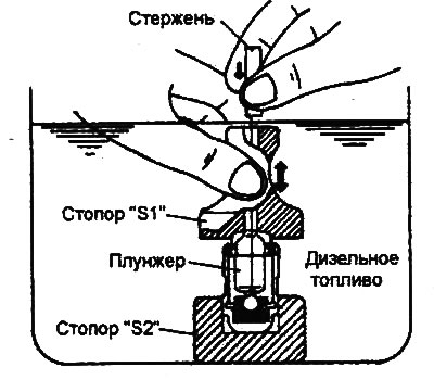
- c) Remove the special tool from the hydraulic compensator. Press the plunger. If it is difficult to move the plunger, the hydraulic compensator is in normal condition. If the plunger moves freely, the air bleeding operation must be repeated. If the plunger still moves freely, replace the hydraulic compensator.
Caution: After completing the air bleeding operation, install the hydraulic compensator vertically upward to prevent diesel fuel from leaking out.
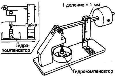
5. After performing the air removal operation, install the hydraulic compensator in a special device (a stand for testing the tightness of the hydraulic compensator).
Note: When installing the hydraulic compensator on the test bench, use the bench adjusting nut to adjust the device to the height of the hydraulic compensator, as shown in the figure.
6. After the hydraulic compensator plunger has dropped by approximately 0.2-0.5 mm, measure the time it takes for the plunger to drop by 1 mm. Replace the hydraulic compensator if the measured time does not correspond to the nominal value.
- Nominal value: 4-20 s (at diesel fuel temperature 15-20°C)
The article is based on information website: HyundaiBook.ru