The main faults of hydraulic valve clearance compensators, their causes and methods of elimination are given in the table.
| Malfunction | Possible reasons | Method of elimination |
| • Temporary noise when starting a cold engine | Normal phenomenon | The noise disappears after the engine oil warms up and reaches normal pressure |
| • Continuous noise after the engine has not been started for 48 hours | Oil leaked from the chambers of the hydraulic valve clearance compensators and air burst in them | The noise will disappear after 15 minutes of engine operation, when the engine crankshaft reaches a speed of 2000–3000 min⁻¹⁻¹
Attention Do not increase engine speed above 3000 rpm⁻¹, as this can damage the hydraulic valve clearance compensators |
| • Continuous noise after engine start and cylinder head replacement | Not enough oil in the engine oil passages | |
| • Continuous noise after prolonged engine starting with the starter or by towing | Oil leaked from the chambers of the hydraulic valve clearance compensators and air got into them | |
| • Continuous noise after replacing hydraulic valve clearance compensators | ||
| • Continuous noise, at idle speed after driving at high speed | Engine oil level is too low or too high | Check the engine oil level |
| A large amount of air is dissolved in the oil after high speed rotation | Check the oil supply system | |
| Deterioration of motor oil properties | Check the quality of the oil. | |
| • The noise continues for more than 15 minutes | Low pressure in the lubrication system | Check the pressure in the lubrication system |
| Hydraulic valve clearance compensators are faulty | Remove the cylinder head and, by pressing on the hydraulic valve clearance compensators, check the amount of their compression Attention Beware of burns from hot hydraulic valve lifters |
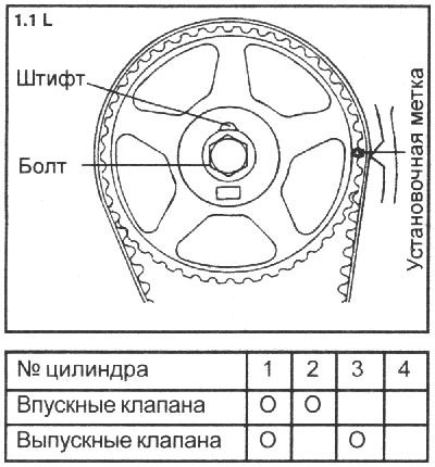
Adjusting valve clearances on 1.1L engines
1. Start the engine and warm it up to operating temperature.
2. Remove the cylinder head cover.
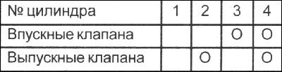
3. Turn the crankshaft clockwise and set the piston in the first cylinder to the top dead center at the end of the compression stroke. In this position, adjust the valve clearances in accordance with the table below.
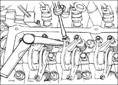
4. Using a flat feeler gauge, measure the clearance between the end of the rocker arm adjusting screw and the end of the valve stem. Adjust the clearance and tighten the screw lock nut.
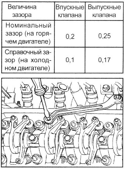
5. Turn the crankshaft one revolution (360°) clockwise to the TDC position of the end of the compression stroke of the piston of the 4th cylinder.
Using a feeler gauge, measure the clearance between the end of the rocker arm adjusting screw and the end of the valve stem. Adjust the clearance and tighten the screw lock nut.
[The publication is borrowed from the website: hyundaibook.ru]
Adjusting clearances at the TDC position of the end of the compression stroke of the piston of the 4th cylinder