Contents: Disassembly ⇓ Examination ⇓ Replacing the valve guide bushing ⇓ Valve seat ⇓ Replacing the valve seat ⇓ Valves ⇓ Assembly ⇓
Disassembly
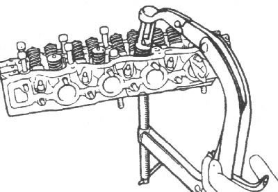
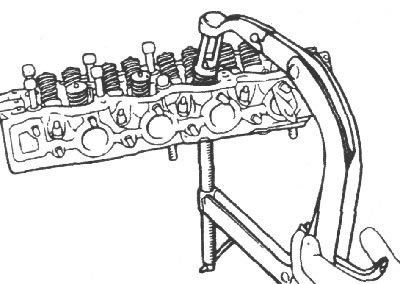
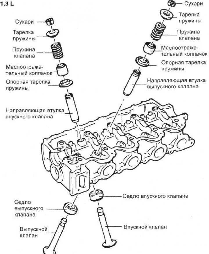
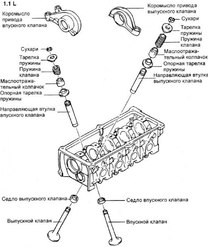
1. Use the special tool to compress the valve spring and remove the valve keepers from the valve stem. Slowly release the spring compressing tool and remove the spring retainer, valve spring, spring seat and valve from the cylinder head.
Note: Have numbered plastic bags or containers available for storing valves.
2. Use pliers to remove the oil deflector cap.
Note: Do not reuse the valve stem seal.
Examination
Valve spring
1. Inspect each valve spring for cracks and damage. Measure the free length of the spring.
2. Place the spring on a flat horizontal surface and measure the deviation of the top of the spring from the vertical plane.
Spring length without load:
- 1.3L engine: 42.03mm
- 1.1L engine: 40.50 mm
- Length of 1.3L engine spring under 24.7 kg load: 34.5 mm
- Length of 1.1L engine spring under 15.6 kg load: 32.0 mm
- Maximum permissible deviation of the spring from the vertical plane: no more than 1.5°
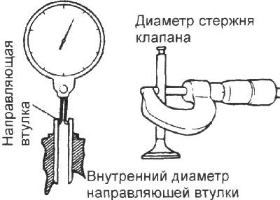
Valve guide bushings
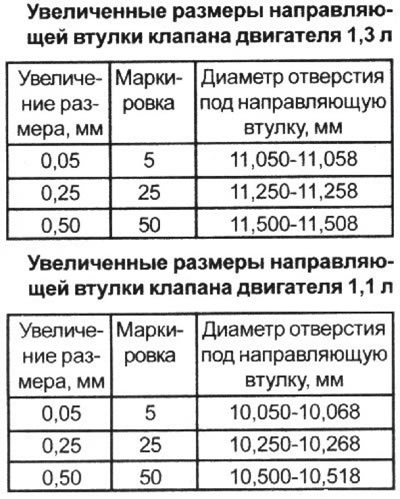
Check the clearance between the stem and the valve guide. If the clearance exceeds the maximum permissible value, replace the valve guide with a larger oversize valve guide.
Clearance between valve stem and valve guide:
- Inlet valves:
- 1.3L engine: 0.030–0.060 mm
- 1.1L engine: 0.020–0.047 mm
- Exhaust valves:
- 1.3L engine: 0.035–0.065 mm
- 1.1L engine: 0.050–0.082 mm
Replacing the valve guide bushing
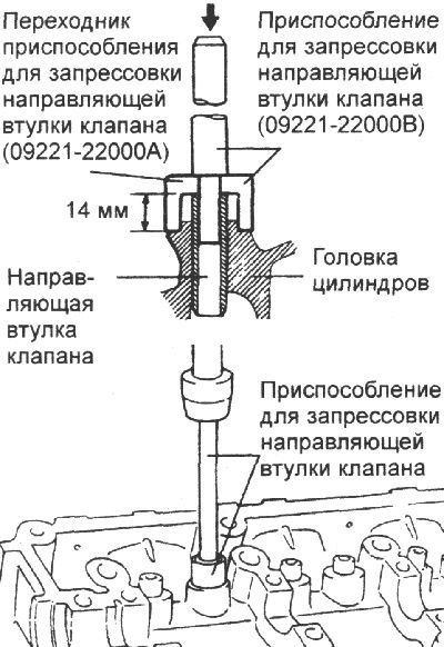
Using tool 09221-21200 (1.3L engine) or 09222-02100 (1.1L engine), replace the guide bushings as follows.
1. Using the guide bushing pressing tool and a press, press the valve bushing out of the cylinder head towards the cylinder block.
2. Ream the hole in the cylinder head to install an oversized bushing.
3. Using the valve guide installation tool, press the valve guide into the cylinder head. The tool ensures that the valve guide is pressed in to a precise depth. Measure the protrusion of the top of the valve guide from the cylinder head. Note that the protrusion of the valve guide is different for intake and exhaust valves.
4. After pressing in the valve guides, insert the new valves and check the clearance.
5. Each time the valve guides are replaced, check and, if necessary, replace the valve seats.
Valve seat
Check the valve seat for overheating and damage to the working surface in contact with the valve disc.
Repair or replace the valve seat if necessary.
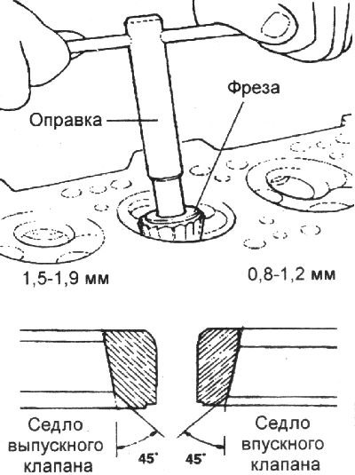
Before machining the Hyundai Getz valve seat, check the valve guide for wear. If the valve guide is worn, replace it and machine the valve seat with a milling cutter, while strictly maintaining the width of the working chamfer and the centering of the seat and the valve guide. After grinding, it is necessary to grind the valve to the seat using lapping paste.
Replacing the valve seat
1. Any valve seat insert that has worn to the limit must be replaced at room temperature by cutting off the wall as shown in Figure A.
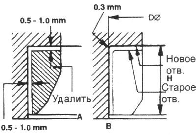
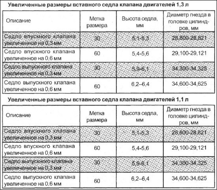
2. After removing the old valve seat, it is necessary to bore the seat to the increased valve seat size. The dimensions for processing are given in the table.
3. Heat the cylinder head to 250°C and press in a new valve seat of the repair size. When pressing in, the valve seat should be at room temperature. After installing the new valve seat, it is necessary to machine its working chamfer and grind in the valve.
Valves
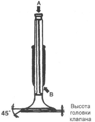
1. Inspect each valve for wear, damage and deformation in the "B" zone and repair or replace if necessary.
If the end face "A" of the rod is pitted or worn, re-chamfer as necessary. This re-chamfer should be limited to minimal metal removal. Also check the thickness of the working edges.
Valve head height, mm:
- nominal height of intake valves:
- 1.3L engine: 1.1
- 1.1L engine: 0.8
- nominal height of exhaust valves:
- 1.3L engine: 1.4
- 1.1L engine: 1.2
- minimum permissible height of intake valves:
- 1.3L engine: 0.8
- 1.1L engine: 0.5
- minimum allowable height of exhaust valves:
- 1.3L engine: 1.1
- 1.1L engine: 0.9
Assembly
Note.
- 1) Clean all parts before installation.
- 2) Apply a thin layer of motor oil to all sliding surfaces.
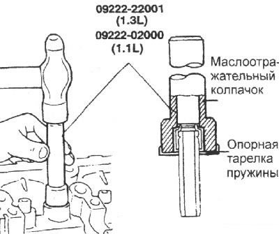
1. Install the spring support plates. Using a special device, install the oil deflector caps on the guide bushings.
The use of the device ensures that the caps are installed in the required position. Incorrect installation of the oil deflector cap adversely affects its working edge due to eccentricity and leads to leakage of engine oil through the valve guides. When installing, be careful not to twist the oil deflector cap.
Do not reuse old valve stem seals.
2. Lubricate the valve stem with engine oil and install the valve. When installing the valve, do not apply too much force to avoid damaging the valve stem seal. Check that the valve moves smoothly.
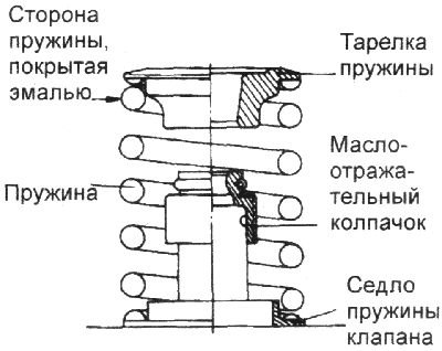
3. Install the springs and spring holders. The springs must be installed with the enamel side facing the plate.
4. Compress the spring with a special tool. Install the crackers and remove the special tool for compressing the spring.
5. Install the cylinder head.