
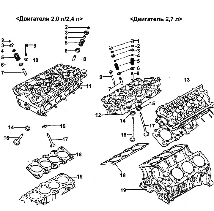
Cylinder head and valves.
1 - hydraulic compensator (2.7 l engine), 2 - crackers, 3 - valve spring plate, 4 - oil seal, 5 - valve spring, 6 - valve spring seat, 7 - exhaust valve guide sleeve, 8 - intake valve guide sleeve, 9 - cylinder head mounting bolt, 10 - washer (2.0 l / 2.4 l engines), 11 - cylinder head (2.0 l / 2.4 l engines), 12 - right cylinder head (2.7 l engine), 13 - left cylinder head (2.7 l engine), 14 - intake valve seat, 15 - exhaust valve seat, 16 - intake valve, 17 - exhaust valve, 18 - cylinder head gasket, 19 - block cylinders.
Disassembly
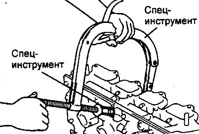
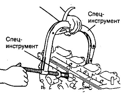
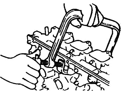
1. Using the special tool (valve spring compressor and adapter), remove the crackers from the valve spring retainer. Then remove the valve spring retainer, valve spring, valve spring seat and valve.
Note: Keep the parts for each valve separately as a set to avoid confusion during installation.
Engines 2.0 l / 2.4 l.
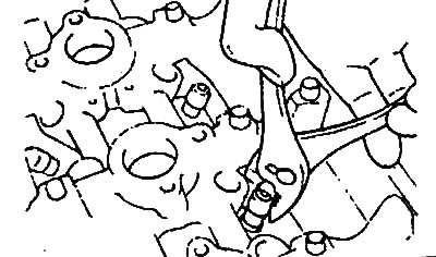
2. Using a special tool (puller), remove the oil seals.
Note: Oil-removing valve caps are not allowed to be reused.
Engines 2.0 l / 2.4 l.
Examination
Cylinder head
1. Check the cylinder head for cracks, damage, and signs of coolant leakage. If cracks are found, replace the cylinder head.
2. Completely clean the cylinder head from scale, carbon deposits and remnants of old sealant and gasket. After cleaning the oil passages, blow them with compressed air to check for clogging.
Engines 2.0 l / 2.4 l.
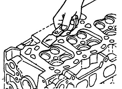
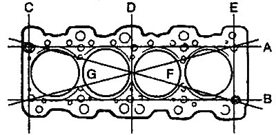
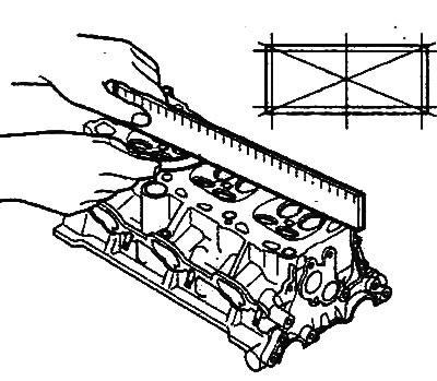
3. Check the cylinder head mating surface for flatness in the directions shown in the figure. If the flatness exceeds the maximum permissible value in any direction, either replace the cylinder head or lightly sand the mating surface of the cylinder head.
Non-flatness of the cylinder head mating surface:
- Nominal value: less than 0.03 mm
- Maximum permissible value:
- 2.0L/2.4L engines: 0.2mm
- 2.7L Engine: 0.05mm
Non-flatness of the mounting surface of the cylinder head for manifolds:
- Nominal value: no more than 0.15 mm
- Maximum permissible value: no more than 0.30 mm
Engines 2.0 l / 2.4 l. |
Engine 2.7 l |
Valves
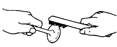
1. Using a wire brush, thoroughly clean the valve.
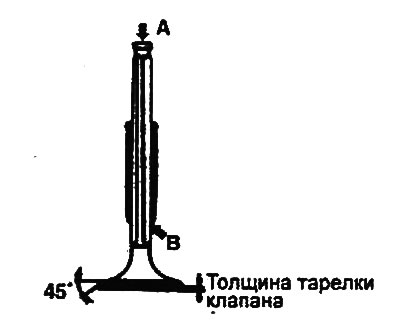
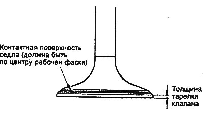
2. Check each valve for wear, damage, and deformation of the valve plate and zone "B" of the valve stem. Replace the valve if necessary. If dents have formed on the end "A" of the valve stem or there is significant wear, then process the end of the valve stem, if necessary. The thickness of the layer removed during mechanical processing of the end of the valve stem should be minimal. In addition, process the working chamfer of the valve seat.
Valve length:
- Nominal value:
- Engines 2.0 p/2.4 l:
- Intake: 109.5 mm
- Exhaust: 109.7 mm
- 2.7L Engine:
- Intake: 96.10 mm
- Exhaust: 97.15mm
Working chamfer angle:
- Nominal value: 45°-45.5°
3. Replace the valve if the valve plate thickness is less than the maximum permissible value.
Valve Plate Thickness:
- Nominal value:
- 2.0L/2.4L Engines:
- Inlet valve: 1.00 mm
- Exhaust valve: 1.50 mm
- 2.7L Engine:
- Inlet valve 1.00 mm
- Exhaust valve 1, 30 mm
- Maximum permissible value:
- 2.0L/2.4L Engines:
- Inlet valve: 0.7 mm
- Exhaust valve: 1.0 mm
- 2.7L Engine:
- Inlet valve: 0.50 mm
- Exhaust valve: 0.80 mm
Checking the valve seat
Check the valve seat for signs of overheating and uneven contact with the working chamfer of the valve plate. If necessary, either restore (machined) or replace the valve seat. Before restoring the valve seat, check the valve guide for wear. If the guide is worn, replace it first, then restore the valve seat.
Valve springs
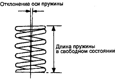
1. Check the free length of each valve spring. If the spring length is less than the maximum allowable value, replace the valve spring.
- Engines 2.0L/2.4L:
- Nominal value:
- Spring length in free state: 45.82 mm
- Spring length under 253N load: 40.00mm
- Maximum permissible value:
- Spring length in free state: 44.82 mm
- 2.7L Engine:
- Nominal value:
- Spring length in free state: 42.5 mm
- Spring length under 219N load: 35.0mm
- Maximum permissible value:
- Spring length in free state: 41.5 mm
- Spring length under 219N load: 34.0mm
2. Using a square, check the deviation of the axis of each spring from the perpendicular to the supporting surface (non-perpendicularity). If the non-perpendicularity is greater than the maximum permissible value, replace the valve spring.
Spring axis deviation (non-perpendicularity):
- Engines 2.0L/2.4L:
- Nominal value: 1.5° or less
- Maximum permissible value: no more than 4°
- 2.7L Engine:
- Nominal value: 1.3° or less
- Maximum permissible value: no more than 3°
Valve guide bushings
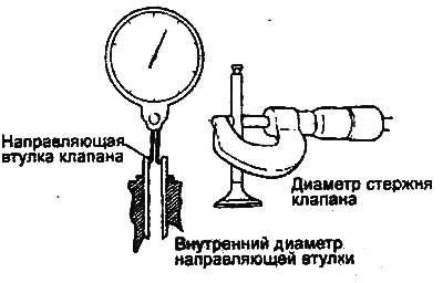
Check the clearance between the valve guide and the valve stem (at several points along the length). If the clearance is greater than the maximum permissible value, replace the valve guide with a bushing of the next repair size.
Clearance between valve guide and valve stem:
- Engines 2.0L/2.4L:
- Nominal value:
- Inlet valve: 0.020-0.047 mm
- Exhaust valve: 0.050-0.085 mm
- Maximum permissible value:
- Inlet valve: 0.10 mm
- Exhaust valve: 0.15 mm
- Engine 2.7L:
- Nominal value:
- Inlet valve: 0.02-0.05 mm
- Exhaust valve: 0.035-0.065 mm
- Maximum permissible value:
- Inlet valve: 0.10 mm
- Exhaust valve: 0.15 mm
Valve stem diameter:
- Nominal value:
- Engine 2.7L:
- Intake: 5.965-5.980 mm
- Exhaust: 5.950-5.965 mm
- 2.0L/2.4L Engines:
- Intake: 6.565-6.580 mm
- Exhaust: 6.530-6.550 mm
Checking hydraulic compensators
1. (2.0L/2.4L engines) The procedure for checking hydraulic lifters is given in the chapter "2.0L/2.4L engines - mechanical part".
2. (2.7L Engine) The procedure for checking hydraulic lifters is given in the chapter "2.7L Engine - Mechanical Part".
Repair
Valve seat restoration
Before reconditioning the valve seat, check the valve guide for wear. If the guide is worn, replace it first, then recondition the valve seat.
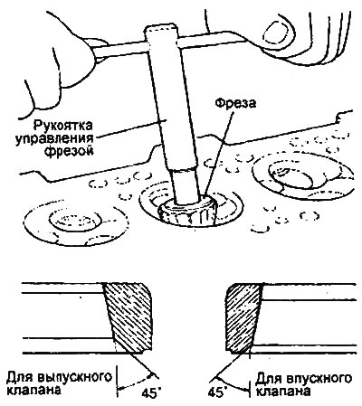
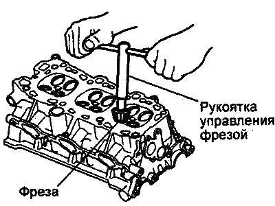
The valve seat is restored using a special tool (milling cutters or machine tools). The width of the valve seat contact surface must correspond to the nominal values and the contact spot must be located evenly along the center of the working chamfer of the valve plate. After restoring the valve seat, the valve and the valve seat must be lapped using lapping paste.
- Valve seat working chamfer angle (2.0L/2.4L): 44°-44.5°
Engines 2.0 l / 2.4 l. |
Engine 2.7 l. |
Replacing the valve seat
Note: Valve seat replacement must be performed on machine tools.
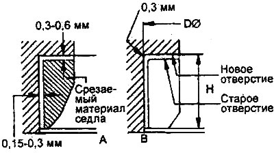
1. Machine (cut) the inside of the valve seat to be replaced to reduce the thickness of its walls.
Engines 2.0 l / 2.4 l. |
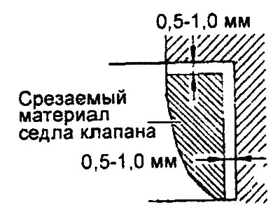
Engine 2.7 l. |
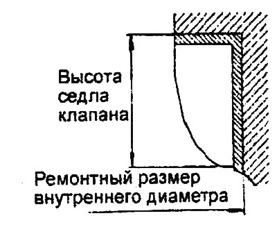
2. Ream the hole in the cylinder head to install a valve seat of the appropriate repair size (increased diameter).
Engine 2.7 l.
3. Heat the cylinder head to approximately 250°C and press a new oversize seat into the cylinder head bore.
The material was obtained from a web resource HyundaiBook.ru
4. Lapping the valve to the new seat using lapping paste.
Valve seat contact surface width:
- 2.0L/2.4L Engines:
- For intake: 0.9-1.3 mm
- For graduation: 0.9-1.3 mm
- 2.7L Engines:
- For intake: 1.1-1.5 mm
- For graduation: 1.3-1.7 mm
Replacing the valve guide
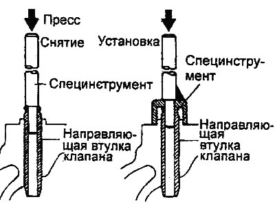
1. Using a special tool (mandrel for installing the valve guide bushing), press out the old valve guide bushing from the cylinder head in the direction of the gasket surface.
2. Ream the cylinder head bore to install a valve guide bushing of the appropriate repair size (increased diameter).
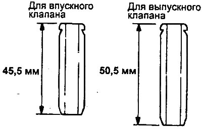
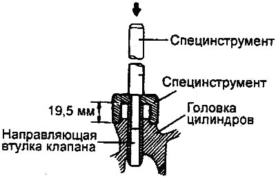
3. Using a special tool (valve guide installation mandrel), press in a new valve guide. The valve guide should be pressed in from the top surface of the cylinder head. Note the difference in length between the intake and exhaust valve guides.
Valve Guide Length:
- Engines 2.0L/2.4L:
- For intake valve: 45.5 mm
- For exhaust valve: 50.5 mm
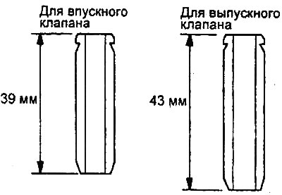
- 2.7L Engine:
- For intake valve: 39.0 mm
- For exhaust valve: 43.0 mm
Note: Do not install a valve guide unless it is the correct oversize.
Engines 2.0 l / 2.4 l. |
Engine 2.7 l. |
Engines 2.0 l / 2.4 l. |
Engine 2.7 l. |
4. After installing the valve guide, insert the new valve and check that the clearance between the guide and the valve stem is within the specified value.
5. After replacing the valve guide, check that the valve is seated correctly in the valve seat. If necessary, treat the valve seat.
Table of repair dimensions of holes for valve seats.
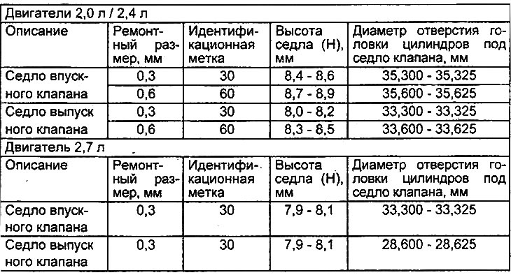
Table. Repair dimensions of valve guide bushings (2.0 l / 2.4 l engines).
| Repair size, mm | Label | Diameter of cylinder head opening for valve guide bushing, mm |
| 0,05 | 5 | 12,050-12,068 |
| 0,25 | 25 | 12,250-12,268 |
| 0,50 | 50 | 12,500-12,518 |
Table. Repair dimensions of valve guide bushings (2.7 l engine).
| Repair size, mm | Label | Diameter of cylinder head opening for valve guide bushing, mm |
| 0,05 | 5 | 11,050-11,068 |
| 0,25 | 25 | 11,250-11,268 |
| 0,50 | 50 | 11,500-11,518 |
Assembly
Note:
- Clean all parts thoroughly before assembly.
- Apply engine oil to all moving and rotating parts.
1. Install the valve spring seat.
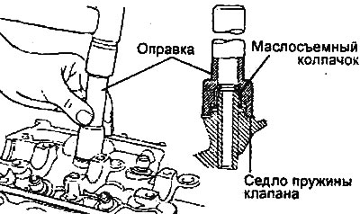
2. Install the oil seal.
Using a special tool (mandrel for installing the oil seal), lightly tap the oil seal into place.
Note:
- Reuse of valve stem seals is not permitted.
- Incorrect installation of the valve stem seal may result in oil leaks through the valve guide.
3. Lubricate the valve stem with engine oil. Insert the valve into the valve guide. Do not force the valve stem through the valve stem seal. After installing the valve, check that it moves smoothly.
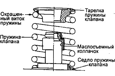
4. Install the valve spring so that the painted spring coil is located near the spring retainer (top), and then install the valve spring retainer.
5. Using the special tool (valve spring compressor and adapter), compress the valve spring and install the crackers. Before removing the special tool after installing the valve, check the reliability of the crackers.
Note: When compressing the valve spring, make sure that the spring plate does not touch the valve stem seal.
Engines 2.0 l / 2.4 l. |
Engine 2.7 l. |