


Removal
Remove the battery.
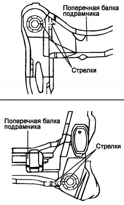
Fig. 2.32. Installing support bushings into the inner tubes of the subframe cross beams
Disconnect the air filter duct (Fig. 2.32).
Disconnect the connectors from the reverse light switch sensor and engine wiring harness.
On models with 5-speed manual transmission, disconnect the reverse light switch sensor connector.
Disconnect the generator wiring harness connectors.
Drain the coolant.
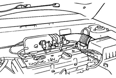
Fig. 2.33. Air filter duct
Note: When disconnecting hoses, always make alignment marks first so that the hoses are in their original position when reconnecting.
Caution: Be careful when disconnecting hoses, do not spill oil or other liquid. Plug disconnected tubes or hoses to prevent foreign particles from getting inside.
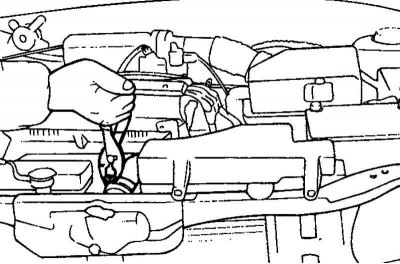
Fig. 2.34. Disconnecting the upper and lower radiator hoses
Disconnect the upper and lower radiator hoses from the engine side, then remove the radiator assembly (Fig. 2.34).
Disconnect the engine ground wire.
Disconnect the brake booster vacuum hose.
Disconnect the main fuel line, fuel return hose and evaporative emission system hose from the engine side.
Disconnect both heater hoses (inlet and outlet) from the engine side.
Disconnect the accelerator pedal cable from the engine side.
On manual transmission models, remove the shift cable from the transmission.
On models with automatic transmission, remove the automatic transmission control cable from the transmission.
Disconnect the speedometer drive cable from the gearbox.
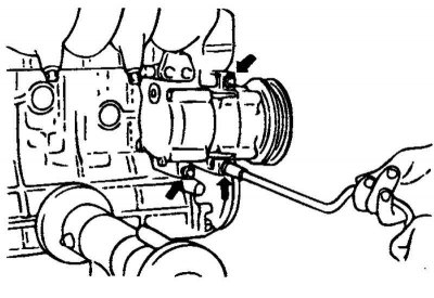
Fig. 2.35. Removing the air conditioning compressor
Disconnect the air conditioner compressor from its mounting bracket (Fig. 2.35).
Jack up the car.
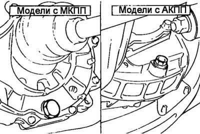
Fig. 2.36. Gearbox drain plugs
Drain the oil or automatic transmission fluid (ATF) from the gearbox (Fig. 2.36).
Disconnect the exhaust pipe from the exhaust manifold.
Note: Use wire to tie the exhaust pipe to the car body.
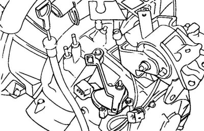
Fig. 2.37. Fastening the gear selection and shift cables
On models with manual transmission, remove the gear selector cable and gear shift cable (Fig. 2.37).
Loosen the bolts securing the ball joint of the lower arm and stabilizer to the lower suspension arm.
Disconnect the wheel drive shafts from the gearbox.
Caution: Cover the drive shaft openings in the gearbox to prevent dirt and foreign particles from entering.
Caution: Before installing the wheel drive shafts, replace the shaft retaining rings.
Using wire, hang the lower arm and wheel drive shaft from the car body.
Using chains or cables, secure the engine to the crossmember by the mounting brackets and hang it on the lift. Raise the engine assembly slightly to relieve the engine mounts of the weight of the power unit before performing the following operations.
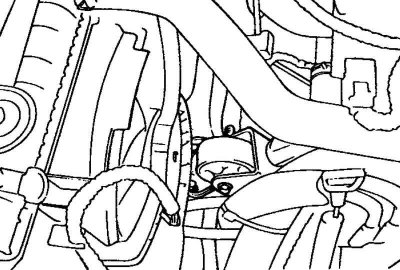
Fig. 2.38. Front engine mount
Remove the front engine mount (Fig. 2.38).
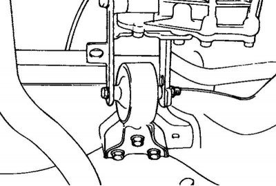
Fig. 2.39. Rear engine support
Disconnect the rear engine support (Fig. 2.39).
Loosen the bolts securing the side engine support.
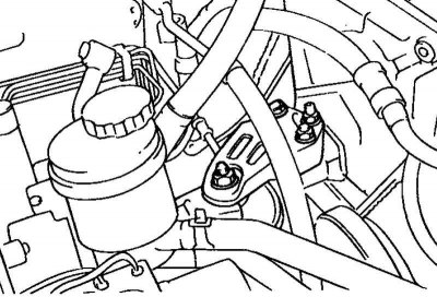
Fig. 2.40. Side support bracket
Remove the side support bracket from the engine (Fig. 2.40).
Slowly lift the engine to relieve the weight of the engine and transmission assembly from the mounts and temporarily leave it suspended.
Caution: Make sure that all cables, wires (electrical connectors), hoses, etc. are disconnected from the engine.
Remove the plugs from inside the left wing splash shield and unscrew the transmission support bracket mounting bolts.
With the transmission facing down, lift the engine and transmission assembly out of the engine compartment and remove it from the vehicle.