
Removal
1. Remove the suction hose and PCV valve.
2. Remove the timing belt cover.
3. Remove the rocker arm cover.
4. Loosen the flange bolts, remove the rocker shaft, rocker arms, and rocker shaft springs as an assembly.
5. Remove the bolts, rocker arms, and rocker arm shaft springs from the shaft.
Examination
Rocker arms
1. Check the roller rotation. If it rotates unevenly or is worn, replace it.
2. Check the surface of the rocker arms. Replace if damaged or deformed.
3. Check the surface of the hydraulic clearance compensator that contacts the valve stem. If worn or damaged, replace the compensator.
Rocker shaft
1. Check the rocker shafts for damage? Replace if necessary.
[Original version of the article on the website HYUNDAIBOOK.RU]
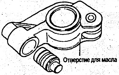
2. Check if the oil hole is clogged.
Automatic gap compensator
1. Insert the air bleed wire into the hole of the automatic compensator and move the plunger up and down 4-5 times.
2. Remove the air bleed wire and use your finger to move the plunger.
If the plunger moves even slightly, repeat steps 1 and 2. If the plunger moves even after repeating steps 1 and 2 multiple times, replace the automatic clearance compensator.
Caution: Do not attempt to disassemble the automatic clearance adjuster. Use clean oil to clean it.
Testing the hydraulic clearance compensator for leaks
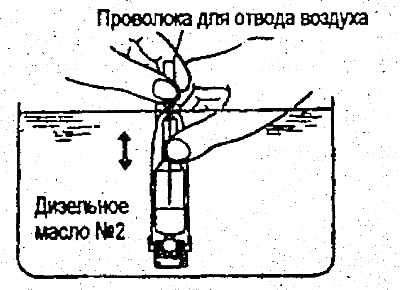
1. Install the hydraulic clearance compensator in a special device (09246-32300), as shown in the figure.
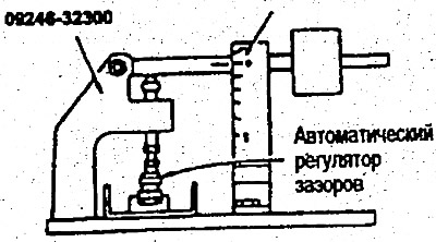
2. After the plunger has dropped slightly, measure the subsequent rate of descent.
The standard value of the rate of descent is 20-50 seconds/2.5 mm
(Diesel oil No.2 or equivalent) - Temperature 27°C
3. If the leak test cannot be performed, check the compensator as follows.
- 1) Check if there is any abnormal noise when the engine is idling at normal operating temperature.
- 2) If the noise is abnormal, bleed the air from the automatic clearance adjuster.
- 3) After releasing the air, check if there is any abnormal noise when the engine is idling at normal operating temperature.
- 4) If the noise is still abnormal, replace the automatic hydraulic clearance compensator.
Installation
1. Install the rocker arms and rocker shaft springs onto the rocker shaft. Install the rocker shaft into the cylinder head.
Tighten the rocker arm shaft mounting bolts to the specified torque.
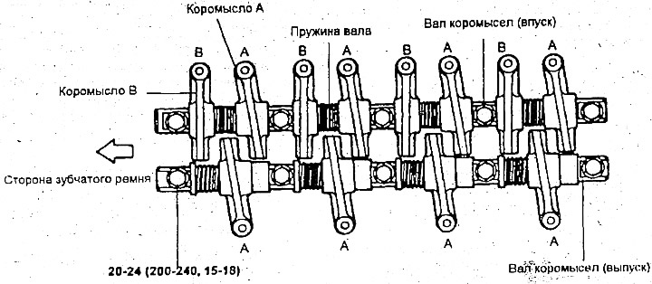
Tightening torque: Rocker shaft mounting bolt - 20-24 Nm
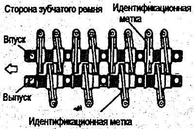
2. When installing rocker arms, shafts, springs, pay attention to the difference between type A and type B rocker arms. Only type A rocker arms are installed on the exhaust side. (See the figure above at the beginning of that section).
3. Install the rocker cover and tighten the bolts to the specified torque.
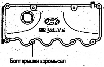
Tightening torque: Rocker cover bolt - 8-10 Nm
Warning:
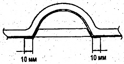
1. Grease should be applied to the top surface of the cylinder head and cover. The surface to be applied is shown in the figure.
2. It is necessary to apply a certain amount of lubricant to prevent it from leaking out.
3. Use special grade grease or equivalent Three bond N1212D aluminum color or equivalent.
4. Install the timing belt cover.
Tightening torque: Timing belt cover bolt - 10-12 Nm
5. Install the air cleaner.
6. Install the suction hose and PCV hose.