
Caution: Broken valve springs and damaged valve stem seals can be replaced without removing the cylinder head. This operation usually requires special tools and a source of compressed air, so please read this section carefully and purchase or rent the necessary tools before starting the job. If you do not have access to a source of compressed air, you can use a piece of nylon rope to prevent the valves from falling into the cylinder while you do this job.
Remove the cover from the cylinder head.
Remove the camshafts and tappets or rocker arm shafts.
Remove all spark plugs.
Turn the crankshaft so that the piston of the desired cylinder is in the TDC position of the compression stroke. When replacing all valve stem seals, start with the first cylinder and work on each cylinder in turn. Move from cylinder to cylinder in firing order (1-3-4-2).
Screw the adapter into the spark plug hole and connect a hose from a compressed air source to it. You can buy such an adapter in many specialized auto stores. Many cylinder compression testers use a screw-in adapter that can be installed in this case.
Direct compressed air into the cylinder.
Caution: The piston may be forced downwards by compressed air, causing the crankshaft to turn unexpectedly. If the wrench used to set the number one piston to TDC is still attached to the bolt at the front end of the crankshaft, it could cause injury if the crankshaft is suddenly turned.
The valves must be held in place using compressed air. If the valve or seat surfaces are in poor condition, leaks may prevent compressed air from holding the valves - refer to the alternative method described below.
If you do not have a source of compressed air, you can use an alternative method. To do this, set the piston to the position before TDC on the compression stroke, then pass a long piece of nylon rope through the spark plug hole until it fills the combustion chamber. Be sure to leave the end of the rope hanging out of the engine so it can be easily removed. Using a large wrench, turn the crankshaft in the normal direction of rotation until a slight resistance is felt.
Place a clean rag in the cylinder head openings above and below the valves to prevent parts and tools from falling into the engine, then use a special spring compressor to compress the spring. Remove the valve keepers with small needle-nose pliers or a magnet.
Remove the spring retainer, valve springs, then remove the valve guide seal. The valves should be held in place with compressed air. If the valve or seat surfaces are in poor condition, leaks may prevent compressed air from holding the valves - refer to the alternative method described below.
If you do not have a source of compressed air, you can use an alternative method. To do this, set the piston to the position before TDC on the compression stroke, then pass a long piece of nylon rope through the spark plug hole until it fills the combustion chamber. Be sure to leave the end of the rope hanging out of the engine so it can be easily removed. Using a large wrench, turn the crankshaft in the normal direction of rotation until a slight resistance is felt.
Place a clean rag in the cylinder head openings above and below the valves to prevent parts and tools from falling into the engine, then use a special spring compressor to compress the spring. Remove the valve keepers with small needle-nose pliers or a magnet.
Remove the spring plate, valve springs, then remove the valve guide bushing seal.
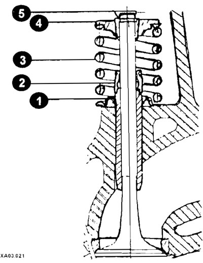
Valve mounting elements
1 - spring seat (bottom plate);
2 - oil seal (oil deflector cap);
3 - spring;
4 - top plate;
5 - crackers.
Caution: If the compressed air pressure does not hold the valve closed during this operation, the valve surface or seat is probably damaged. If this is the case, the cylinder head will have to be removed to perform repairs.
Place a rubber band or tape around the top of the valve stem to prevent the valve from falling into the combustion chamber, then shut off the air supply to the engine cylinder.
Caution: If a nylon rope was used instead of air pressure, turn the crankshaft slightly in the direction opposite to normal rotation.
Check the valve stem for damage. Rotate the valve in the guide bushing and check for movement of the eccentric at the end, which would indicate that the valve is bent.
Move the valve up and down in the guide bushing and make sure it does not stick. If the valve stem sticks, it means either the valve is bent or the guide bushing is damaged. In any case, it is necessary to remove the head for repair. •Reapply air pressure to the cylinder to hold the valve in the closed position, then remove the rubber band or film from the valve stem. If a nylon rope was used, turn the crankshaft in the direction of normal rotation until a slight resistance is felt.
Place the springs back on top of the valve.
Lubricate the valve stem with engine oil and install a new seal.
Install the spring mount (crackers). Compress the spring with a puller and carefully insert the crackers into the groove. Apply a small amount of grease to the inside surface of each cracker to hold it in place.
Relieve pressure from the compressor and ensure that the crackers are properly seated.
Use a rubber hammer to tap the valve.
Disconnect the compressed air hose and remove the adapter from the spark plug hole. If a nylon rope was used instead of compressed air, remove it from the cylinder.
Install the camshafts, tappets or rocker arms.
Install the spark plugs and connect the high tension wires.
Install the cylinder head cover.
Start the engine and let it run, then check for leaks and/or unusual sounds coming from the valve cover.
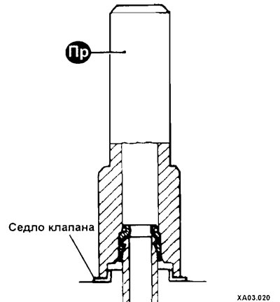
Installing the seal using a tool