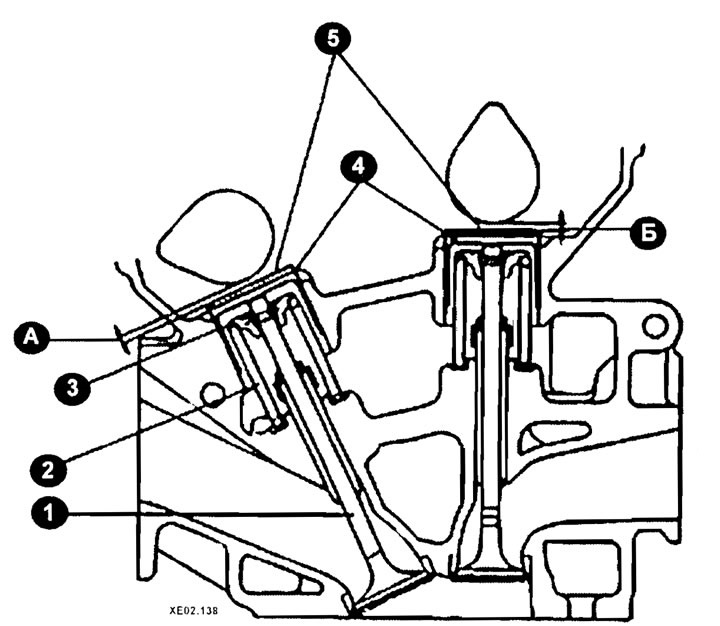
Elements of the gas distribution mechanism of 2.0 liter engines of 2001-2005 release
A, B - adjustable gap;
1 - valve;
2 - spring;
3 - crackers;
4 - pusher;
5 - adjusting washer.
Valve clearance is one of the factors that determines how long the intake and exhaust valves will be open.
If the valve clearance is too large, then part of the stroke of the tappet and camshaft will be spent on compensating for the excess clearance, i.e. the valves will not be open long enough. This will cause two effects: the valve drive mechanism parts will make a knocking sound, the engine will run poorly because the intake valve will not open sufficiently, and less of the working mixture will enter the cylinder. Insufficient opening of the exhaust valve will lead to excess exhaust gas pressure in the cylinder, which will prevent the required amount of working mixture from entering the cylinder.
If the valve clearance is too small, the intake and exhaust valves do not fit tightly in the cylinder head when they are closed. When the valve sits in the cylinder head, it performs two functions - it closes the combustion chamber so that no gases can escape from the cylinder, and it cools itself by absorbing some of the heat from the combustion process by the cylinder head and the engine cooling system. So if the valve clearance is too small, the engine will run poorly (due to gases escaping from the combustion chamber), and the valve will overheat and deform (because it cannot transfer heat until it touches the valve seat in the cylinder head).
Caution: While all valve adjustments should be made with the utmost care, it is better to have a looser adjustment than a tighter one, as burnt valves are the result of a tighter adjustment.
Valve clearances must be checked/adjusted periodically during vehicle operation, as well as after engine repairs related to the valve timing mechanism.
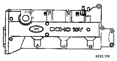
If the engine is in the vehicle, remove the air filter. Also remove the cylinder head cover. If you do this carefully, you can avoid damaging the gasket.
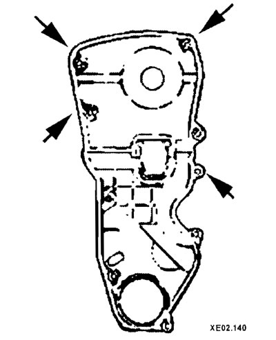
Remove the front timing belt cover.
Adjusting the clearance involves selecting the valve tappet adjusting washer until the required clearance value is achieved.
Note: The clearance must be checked and adjusted on a cold engine (engine coolant temperature is 15-25°C). At this temperature, the valve clearances should be 0.2 mm for the intake valves and 0.28 mm for the exhaust valves.
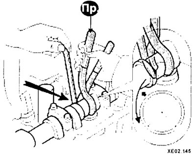
Turn the crankshaft clockwise using a wrench until the marks on the crankshaft gear align with the protrusion on the rear cover.
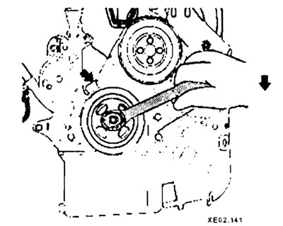
In this position, the timing marks of camshafts A and B should match, and the marked chain links (arrows) should be located on top (see the picture on the next page. p.).
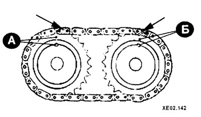
If this is not the case, turn the crankshaft one more revolution.
By inserting a feeler gauge between the cam and the adjusting washer, check the clearances on the cams (1, 2, 3) of the camshafts shown in the figure.
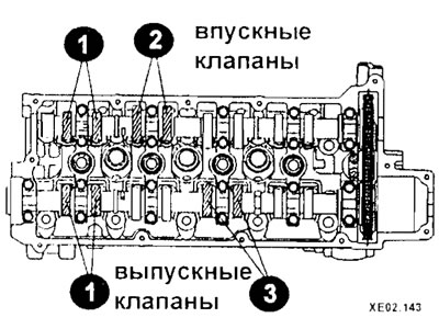
The probe should move with a slight pinch.
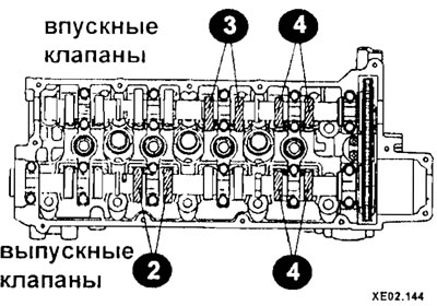
Turn the crankshaft 360° and measure the valve clearances on the cams (2, 3, 4) shown in the figure.
If the measured clearance is within tolerance, there is no need to replace the adjusting shims. If the clearance differs from the required value, replace the valve tappet adjusting washer.
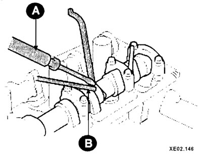
Rotate the tappet so that its cutout faces the center of the cylinder head. This will make it easier to remove the washer.
Using a special mandrel, press the pusher with the valve down.
Insert the locking mandrel (clamp) between the edge of the tappet and the camshaft.
Using a narrow-blade screwdriver (A) and a magnet (B), remove the adjusting washer from the tappet using the slot in the tappet.
Determine the required thickness of the new washer using the formula:
- N=R+(M-0.2 mm) — for intake valves;
- N=R+(M-0.28 mm) — for exhaust valves,
where R is the thickness of the old washer, N is the thickness of the new washer, M is the measured valve clearance.
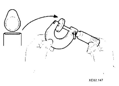
Use a micrometer to determine the thickness of the removed washer (see picture on the right).
Spare parts include washers with a thickness from 3 mm to 4.5 mm with a step of 0.05 mm.
Select a new washer with a thickness closest to the calculated value.
Install a new washer using a suitable tool.
Note: The numbered surface of the washer must face down.
With the tappet retaining tool removed, recheck the valve clearance.
Turning the crankshaft 180° each time, check and adjust the clearances of the remaining cams in pairs in the following sequence: 5-2; 8-6; 4-7.
After checking/adjusting the valve clearance, pour oil into the cylinder head baths and reinstall the previously removed elements.