
Contents: Disassembly ⇓ Examination ⇓ Replacing the valve seat ⇓ Replacing the valve guide bushing ⇓ Assembly ⇓
Disassembly
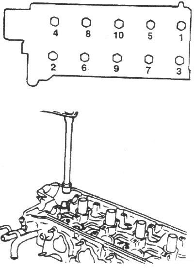
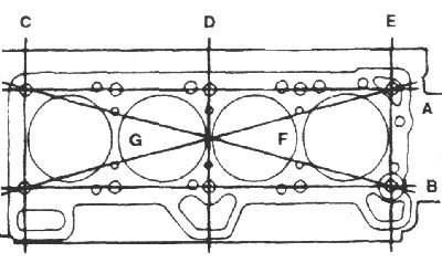
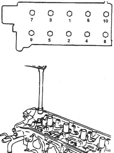
1. Using a special tool, in the sequence shown in the figure, in 2–3 passes, unscrew the cylinder head mounting bolts.
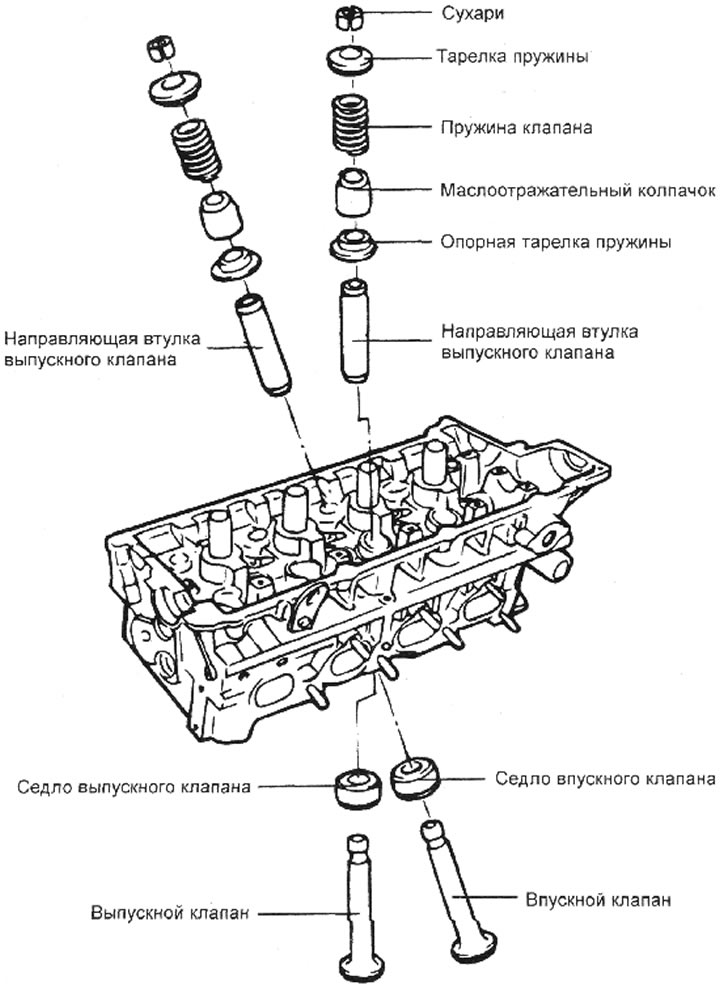
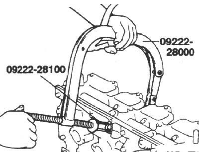
2. Using the special tool, compress the valve spring and remove the valve cotters from the valve stem. Slowly release the spring compressing tool and remove the spring retainer, valve spring, spring support retainer and valve from the cylinder head.
Note: Have numbered plastic bags or containers available for storing valves.
3. Use pliers to remove the oil deflector cap.
Note: Do not reuse the valve stem seal.
Examination
Cylinder head
1. Inspect the cylinder head for damage, cracks, oil and coolant leaks. Replace the cylinder head if necessary.
2. Remove scale, sealant and carbon deposits. Blow out the lubrication channels with compressed air. Check the cylinder head flatness in six directions A, B... with a metal ruler and feeler gauge.
If necessary, regrind the cylinder head.
- Standard deviation from flatness: less than 0.03 mm
- Maximum permissible deviation from flatness: less than 0.20 mm
Valves
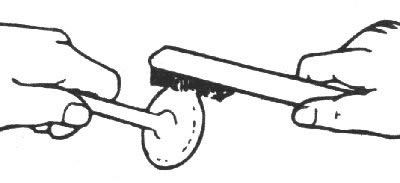
1. Use a wire brush to clean the valve.
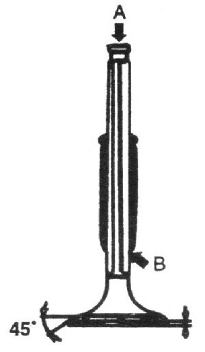
2. Inspect each valve for wear, damage and deformation in the "B" zone and repair or replace if necessary.
If the end "A" of the stem is pitted or worn, re-chamfer as necessary. This re-chamfer should be limited to minimal metal removal. Also check the thickness of the cylinder portion of the valve head.
Nominal thickness of the cylindrical part of the valve head, mm
- inlet valves: 1.1
- exhaust valves: 1.3
Minimum permissible thickness of the cylindrical part of the valve head, mm
- inlet valves: 0.8
- exhaust valves: 1.0
Valve spring
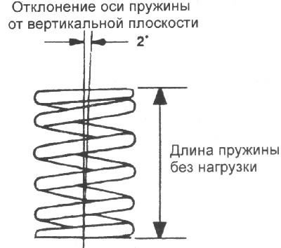
1. Inspect each valve spring for cracks and damage. Measure the free length of the spring.
2. Place the spring on a flat horizontal surface and measure the deviation of the top of the spring from the vertical plane.
- Spring length without load: 44 mm
- Spring length under 21.6 kg load: 35.0 mm
- Spring length under 41.5 kg load: 27.2 mm
- Deviation of the spring axis from the vertical plane: no more than 1.5°
- Maximum permissible reduction in the length of the spring without load: -1 mm
- Maximum permissible deviation of the spring axis from the vertical plane: no more than 4°
Valve guide bushings
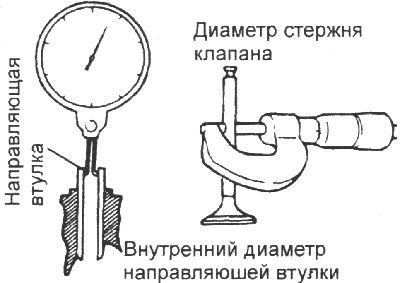
Check the clearance between the stem and the valve guide. If the clearance exceeds the maximum permissible value, replace the valve guide with a larger oversize valve guide.
Nominal clearance between the guide sleeve and the valve stem, mm:
- intake valves: 0.03–0.06
- exhaust valves: 0.05–0.08
Maximum permissible clearance between the guide bushing and the valve stem, mm:
- intake valves: 0.1
- exhaust valves: 0.15
Valve seat
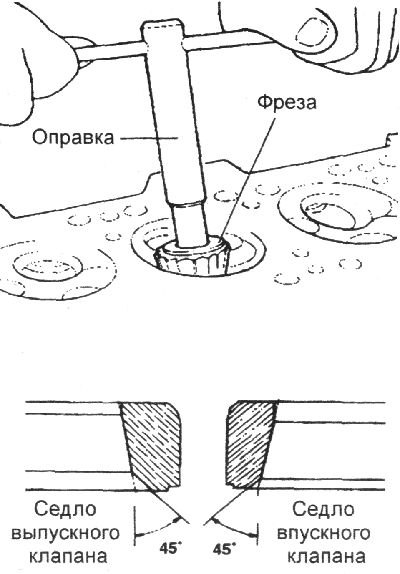
Check the valve seat for overheating and damage to the working surface that contacts the valve disc. Repair or replace the valve seat if necessary.
Before machining the valve seat, check the valve guide for wear. If the valve guide is worn, replace it and machine the valve seat with a milling cutter, while strictly maintaining the width of the working chamfer and the centering of the seat and the valve guide. After grinding, it is necessary to grind the valve to the seat using lapping paste.
Replacing the valve seat
1. Any valve seat insert that has worn to the limit must be replaced at room temperature by cutting off the wall as shown in the figure.
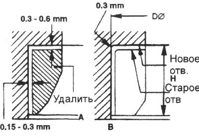
2. After removing the old valve seat, it is necessary to bore the seat to the increased valve seat size. The dimensions for processing are given in the table.
3. Heat the cylinder head to 250°C and press in a new valve seat of the repair size. When pressing in, the valve seat should be at room temperature. After installing the new valve seat, its working chamfer must be machined.
4. Lapping the valve to the new seat using lapping paste.
Width of the working chamfer of the valve seat, mm:
- intake valves: 0.8–1.2
- exhaust valves: 1.3–1.7
Replacing the valve guide bushing
1. Using the guide bushing pressing tool and a press, press the valve bushing out of the cylinder head towards the cylinder block.
2. Using tool 09221–22000 A/B, press the valve guide out of the cylinder head toward the cylinder block.
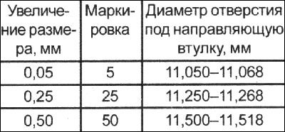
3. Ream the hole in the cylinder head to install the oversized bushing.
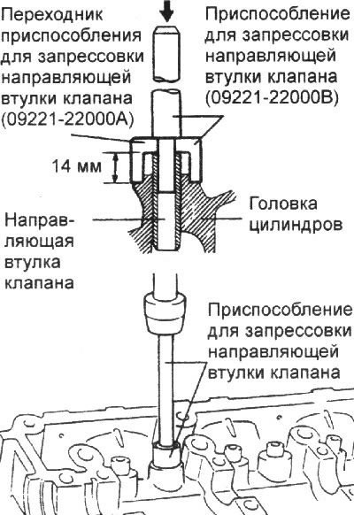
4. Using the valve guide installation tool 09221–22000 A/B, press the guide into the top of the cylinder head.
5. After pressing in the valve guide bushings, insert the new valves and check the clearance between its stem and the guide bushing.
6. After replacing the guide bushing, check that the valve is correctly positioned in the seat. If necessary, grind the valve seat.
Increased valve guide dimensions
Assembly
Note.
- 1) Clean all parts before installation.
- 2) Apply a thin layer of motor oil to all sliding surfaces.
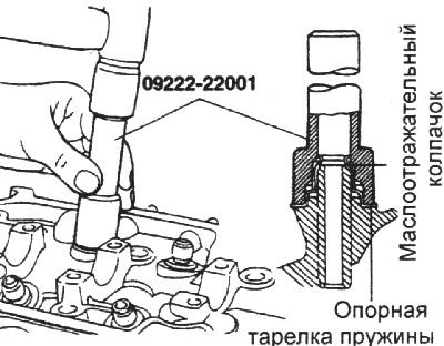
1. Install the spring support plates.
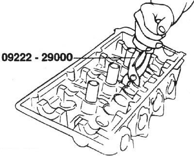
Using light hammer blows on the mandrel of tool 09222–22001, press the oil deflector caps onto the guide bushings.
Note.
- Do not reuse old valve stem seals.
- Incorrect installation of the valve stem seal will adversely affect its working edge due to eccentricity and will result in engine oil leakage through the valve guides.
2. Lubricate the valve stem with engine oil and install the valve. When installing the valve, do not apply too much force to avoid damaging the valve stem seal. Check that the valve moves smoothly.
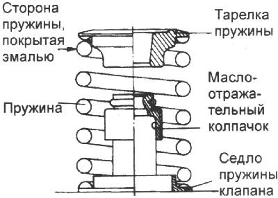
3. Install the springs and spring plates. The springs must be installed with the enamel side facing the plate.
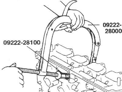
4. Compress the spring using special tool 09222–28000, 09222–28100. Install the crackers and remove the special tool for compressing the spring.
Note: When compressing the spring, make sure that the oil seal is not pinched by the spring compressor.
Increased dimensions of the valve seat insert
| Description | Size label | Saddle height, mm | Cylinder head socket diameter, mm |
| Inlet valve seat increased by 0.3 mm | 30 | 5,1–5,3 | 30,700–30,721 |
| Inlet valve seat increased by 0.6 mm | 60 | 5,4–5,6 | 31,000–31,021 |
| Exhaust valve seat increased by 0.3 mm | 30 | 6,2–6,4 | 27,300–27,321 |
| Exhaust valve seat increased by 0.6 mm | 60 | 6,5–6,7 | 27,600–27,621 |
5. Clean all mating surfaces of the cylinder block and cylinder head.
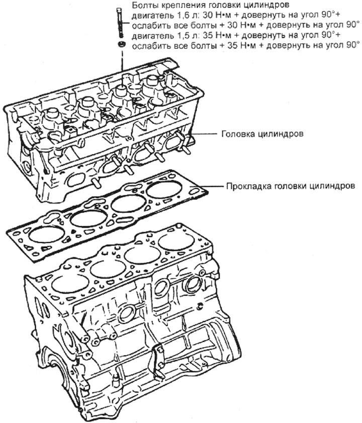
6. Check for markings on the cylinder head gasket.
7. Install the new cylinder head gasket with the marked surface facing the cylinder head.
8. Tighten the cylinder head bolts in the sequence shown in the figure.
Tightening torques for cylinder head bolts:
- 1.6L engine: 30 Nm + turn further by 90° + loosen all bolts + 30 Nm + turn further by 90°
- 1.5L engine: 35Nm + turn 90° further + loosen all bolts + 35Nm + turn 90° further