
Disassembly
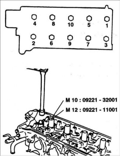
1. With a special tool 09221–32001, 09221–11000, in the sequence shown in the figure, remove the cylinder head bolts in 2–3 passes.
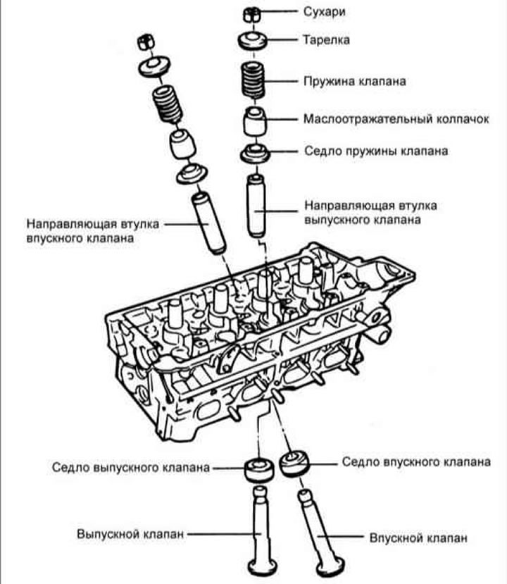
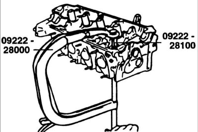
2. Using the special tool 09222-28000, 09222-28100, compress the valve spring and remove the crackers from the valve stem. Slowly release the spring compressor and remove the valve spring, spring cap and valve from the cylinder head.
Attention! Have numbered plastic bags or containers ready to store the valves.
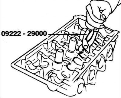
3. Use pliers 09222–29000 to remove the oil seal.
Attention! Do not reuse the oil seal.
Examination
Cylinder head
1. Inspect the cylinder head for damage, cracks, oil and coolant leaks. If necessary, replace the cylinder head.
2. Remove scale, sealant and carbon deposits. Blow out the lubrication channels with compressed air.
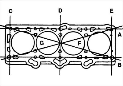
3. With a metal ruler and feeler gauge in the six directions A, B... check the flatness of the cylinder head. Regrind the cylinder head if necessary.
- Standard deviation from flatness: less than 0.03 mm.
- Maximum permissible deviation from flatness: 0.05 mm.
Valves
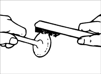
1. Clean the valve with a wire brush.
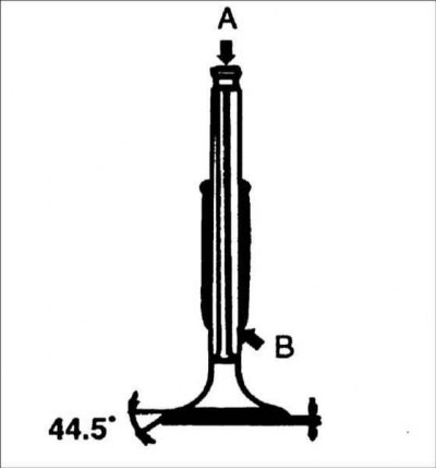
2. Inspect each valve for wear, damage, and deformation in areas A and B and repair or replace as necessary. If the end of the rod is corroded or worn, restore the chamfers as necessary. This recovery should be limited to minimal metal removal.
Also check the thickness of the working edges.
Valve lip thickness:
- Intake valves: 1.15mm:
- 1.8 and 2.0 L engines: 1.15 mm;
- 1.6L engines: 1.1mm.
- Exhaust valves:
- 1.8 and 2.0 L engines: 1.35 mm;
- 1.6 L engines: 1.3 mm.
Maximum permissible thickness of the valve working edge:
- Inlet valves: 0.8mm;
- Exhaust valves: 1.0 mm.
Valve spring
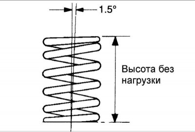
1. Inspect each valve spring for cracks or damage. Measure the free length of the spring.
2. Install the spring on a flat horizontal surface and measure the deviation of the top of the spring from the vertical plane.
Engines 1.8 and 2.0 l
- Spring length without load: 48.86 mm
- Spring length under load 18.3 kg: 39 mm
- Spring length under load 40.0 kg: 30.5 mm
- Permissible deviation of the spring from the vertical plane: no more than 1.5°
- Maximum permissible deviation of the spring from the vertical plane: no more than 3°
1.6L engines
- Spring length without load: 44mm
- Spring length under load 21.6 kg: 35 mm
- Spring length under load 45.1 kg: 27.2 mm
- Permissible deviation of the spring from the vertical plane: no more than 1.5°
- Maximum permissible deviation of the spring from the vertical plane: no more than 4°
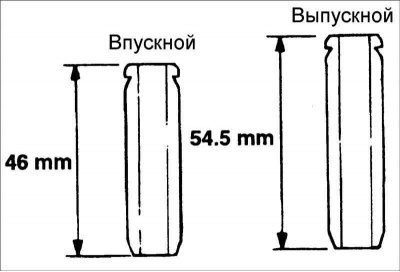
Valve guides
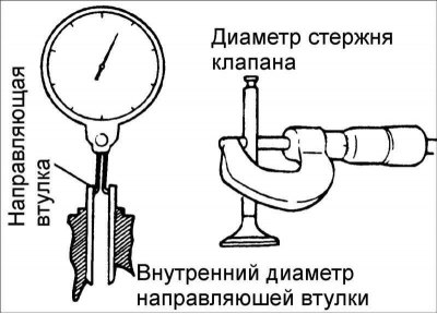
Check clearance between valve stem and valve guide. If the clearance exceeds the limit, replace the valve guide with an oversized bushing.
Engines 1.8 and 2.0 l
Clearance between stem and valve guide:
- Inlet valves: 0.02–0.05 mm
- Exhaust valves: 0.035-0.065mm
Maximum allowable clearance between valve stem and valve guide:
- Inlet valves: 0.1mm
- Exhaust valves: 0.13mm
1.6L engines
Clearance between stem and valve guide:
- Inlet valves: 0.03–0.06 mm
- Exhaust valves: 0.05-0.08 mm
Maximum allowable clearance between valve stem and valve guide:
- Inlet valves: 0.1mm
- Exhaust valves: 0.15mm
Insert valve seat
Check the valve seat for overheating and damage to the seat in contact with the valve disc. Repair or replace the valve seat if necessary.
Before replacing or repairing the valve seat, check the valve guide for wear. If the valve guide is worn, replace it.
Valve seat replacement
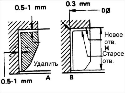
Any valve seat insert worn to the limit must be replaced at room temperature by shearing the wall as shown.
2. After removing the old valve seat, it is necessary to bore out the seat for the oversized valve seat. Dimensions for processing are shown in the table.
Oversized valve seat insert for 1.8 and 2.0L engines3
Description | size mark | Saddle height, mm | Diameter of a nest in a head of cylinders, mm |
| Inlet valve seat, increased by 0.3 mm | 30 | 7,5–7,7 | 33,300–33,325 |
| Inlet valve seat, increased by 0.6 mm | 60 | 7,8–8,0 | 33,600–33,625 |
| Exhaust valve seat, enlarged by 0.3 mm | 30 | 7,9–8,1 | 28,800–28,821 |
| Exhaust valve seat, enlarged by 0.6 mm | 60 | 8,2–8,4 | 29,100–29,121 |
Oversized valve seat insert for 1.6L engines
Description | size mark | Saddle height, mm | Diameter of a nest in a head of cylinders, mm |
| Inlet valve seat, increased by 0.3 mm | 30 | 5,1–5,3 | 30,700–30,721 |
| Inlet valve seat, increased by 0.6 mm | 60 | 5,4–5,6 | 31,000–31,021 |
| Exhaust valve seat, enlarged by 0.3 mm | 30 | 6,2–6,4 | 27,300–27,3211 |
| Exhaust valve seat, enlarged by 0.6 mm | 60 | 6,5–6,7 | 27,600–27,621 |
3. Heat the cylinder head to 250°C and press in a new oversize valve seat. The valve seat must be at room temperature when pressed in.
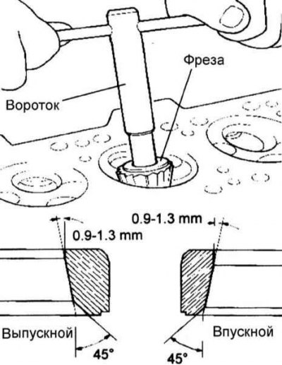
4. After installing a new valve seat, the valve must be lapped. The width of the chamfer of the valve seat must be within the specifications.
The width of the working chamfer of the inlet valve seat:
- engines 1.8 and 2.0 l: 1.1–1.5 mm;
- 1.6L engines: 0.8–1.2 mm.
Exhaust valve seat bevel width: 1.3–1.7 mm
Valve Guide Replacement
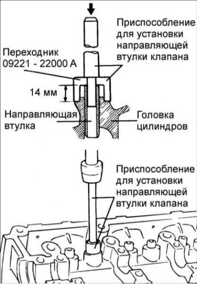
1. Using tool 09221-22000 A/B, press the valve bushing out of the cylinder head towards the cylinder block.
2. Fit a new oversized valve guide to the cylinder head bore.
3. Using the valve guide installer 09221-22000 A/B, press the valve guide into the cylinder head. The device ensures that the bushing is pressed to a strictly defined depth. Measure the protrusion of the top of the valve guide from the cylinder head. Note that valve guide protrusion is different for intake and exhaust valves.
4. After pressing in the valve guides, insert the new valves and check the clearance.
5. Check and, if necessary, replace the valve seats each time the valve guides are replaced.
Oversized valve guide
Increased sizes | size mark | Cylinder head bore diameter |
0,05 | 5 | 11,050–11,068 |
0,25 | 25 | 11,250–11,268 |
0,5 | 50 | 11,500–11,518 |
Assembly
- 1. Clean all parts before installation.
- 2. Apply a light coat of engine oil to all sliding surfaces.
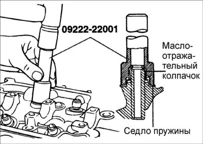
1. Install the spring seat. Using special tool 09222-22001, install the oil seal.
- 1. Do not reuse old oil seals.
- 2. Incorrect installation of the valve stem seal adversely affects its sealing lip due to eccentricity and causes engine oil to leak through the valve guides.
When installing, be careful not to twist the oil seal.
2. Lubricate the valve stem with engine oil and install the valve. When installing the valve, do not apply much force so as not to damage the oil seal. Check for smooth valve movement.
3. Install springs and spring retainers. The springs must be installed with the enameled side towards the spring holders.
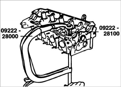
4. Use the special tool 09222-28000, 09222-28100 to compress the spring. Install crackers and remove the special device for spring compression.
Attention! When compressing the spring, make sure the slinger cap is not pinched by the spring compressor.
5. Clean all mating surfaces of the cylinder block and cylinder head.
6. Check up presence of marking on a laying of a head of cylinders.
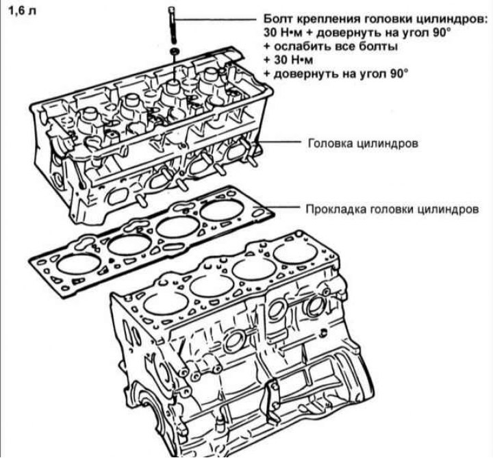
7. Install a new cylinder head gasket with the marked surface toward the cylinder head.
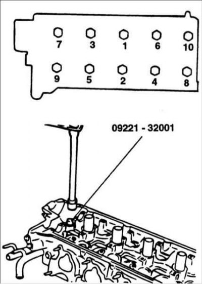
8. In the sequence shown in the figure, tighten the cylinder head bolts.
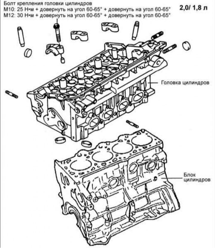
Tightening torque of the cylinder head bolts for 1.8 and 2.0 l engines:
- M10: 25 Nm tighten by 60–65°tighten by 60–65°
- M12: 30 Nm tighten by 60–65°tighten by 60–65°
Tightening torque of the cylinder head bolts for 1.6 l engines:
- 30 Nm turn 90°loosen all screws 30 Nm turn 90°