
Disassembly
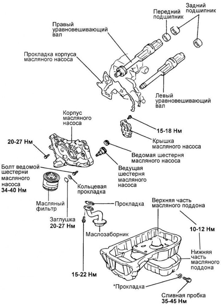
Pic. 2.85. Oil pump housing, oil pump and balance shafts
Oil pump housing, oil pump and balance shafts, see fig. 2.85.
Remove the timing belt.
Loosen the oil pan mounting bolts.
Use a rubber mallet to knock down the pallet and remove both parts of it.
Remove the oil pickup and its gasket.
Pic. 2.86. Removing the oil pressure switch
Remove the oil pressure switch (pic. 2.86).
Remove the oil filter bracket and its gasket.
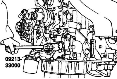
Pic. 2.87. Removing the oil pump plug in the front cover
With a special key (09213-33000) unscrew the oil pump plug in the front cover (pic. 2.87).
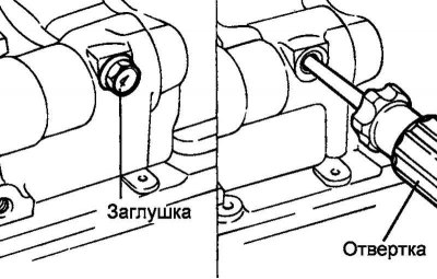
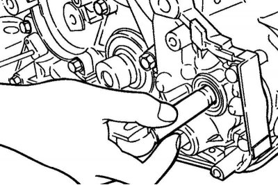
Pic. 2.88. Removing the plug and installing a screwdriver
Unscrew the plug on the left side of the cylinder block and insert an 8 mm screwdriver into the hole in the plug. The screwdriver must go to a depth of more than 60 mm (pic. 2.88).
Pic. 2.89. Removal of a bolt of fastening of the left counterbalancing shaft
Turn away a bolt of fastening of a conducted gear wheel of the oil pump and the left counterbalancing shaft (pic. 2.89).
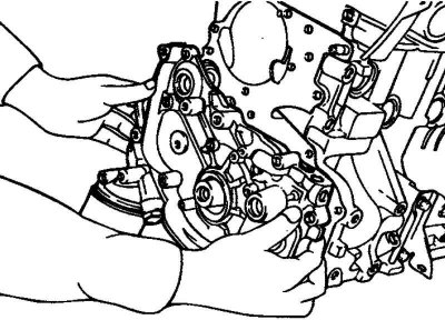
Pic. 2.90. Removing the front cover
Loosen the front cover screws. Remove cover and gasket (pic. 2.90).
Remove both balance shafts.
Remove the oil pump cover from the front cover.
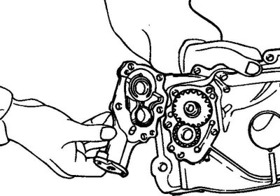
Pic. 2.91. Removing the oil pump gears
Remove oil pump gears (pic. 2.91).
Remove the screwdriver from the plug hole on the left side of the cylinder block.
Checking the Front Cover
Check the condition of the cover oil passages. Clean if necessary.
Check the condition of the balance shaft front bearing. For any bearing failure, replace the front cover.
Check for cover cracks or other damage.
Replace the front cover if necessary.
Checking the balance shafts
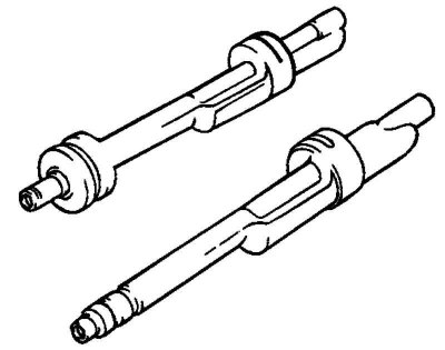
Pic. 2.92. Balance shafts
Check for wear or tear on the journals of the balance shafts (pic. 2.92).
If there is a seizure of the necks, carefully check the condition of the bearings.
Replace bearings or balance shaft if necessary.
Checking the stuffing box
Check the seal lip for deterioration. Replace the seal if necessary.
Checking the oil pressure switch
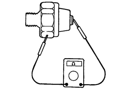
Pic. 2.93. Checking the oil pressure switch
Using an ohmmeter, check for a closed circuit between the terminal and the sensor-switch housing. If the circuit is open, replace the sensor-switch (pic. 2.93).
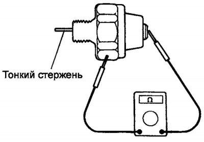
Pic. 2.94. Installing a thin rod in the sensor-switch hole
Insert a thin rod into the opening of the sensor-switch and press on the diaphragm. If the circuit remains closed between the output and the sensor-switch body, replace the sensor-switch (pic. 2.94).
If the circuit between the output and the body of the sensor-switch is open, when a vacuum of 50 kPa acts on the diaphragm of the sensor-switch, then the sensor-switch is working. If the vacuum is not maintained, then the sensor diaphragm is destroyed. Replace sensor switch.
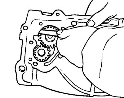
Oil pump check
Install the oil pump gears into the front cover. Check the smoothness of rotation of the gears and the absence of a significant gap in the engagement.
Check for annular wear on the end surfaces of the front cover and oil pump cover (gear contact points).
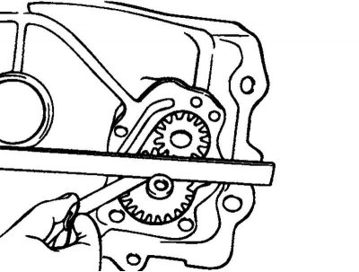
Pic. 2.95. Measuring the clearance between the pump housing and the tops of the gear teeth
Measure the clearance between the pump housing and the tops of the gear teeth (pic. 2.95).
Rated Clearance:
- Drive gear - 0.16-0.21 mm
- Driven gear - 0.18-0.21 mm
Limit clearance:
- Drive gear - 0.25 mm
- Driven gear - 0.25 mm
Pic. 2.96. End clearance measurement
Measure end clearance (pic. 2.96).
Rated Clearance:
- Drive gear - 0.08-0.14 mm
- Driven gear - 0.06-0.12 mm
Limit clearance:
- Drive gear - 0.25 mm
- Driven gear - 0.25 mm
Balance Shaft Bearing Replacement
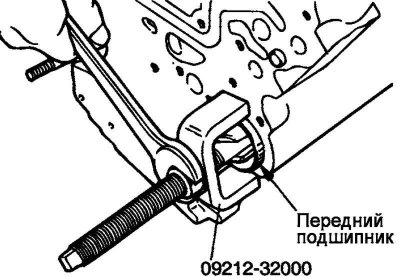
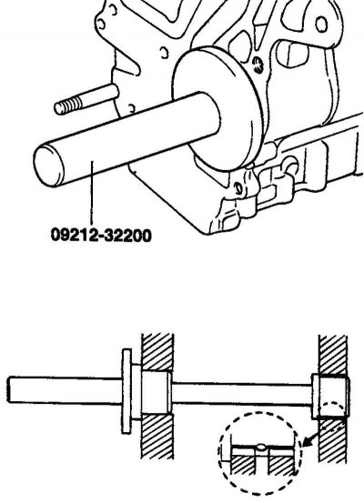
Pic. 2.97. Dismantling the front bearing of the right balance shaft
Using a special tool, dismantle the front bearing of the right balance shaft from the cylinder block (pic. 2.97).
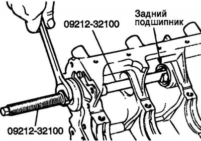
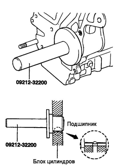
Pic. 2.98. Dismantling the rear bearing of the right balance shaft
Using a special tool, remove the rear bearing of the right balance shaft from the cylinder block (pic. 2.98).
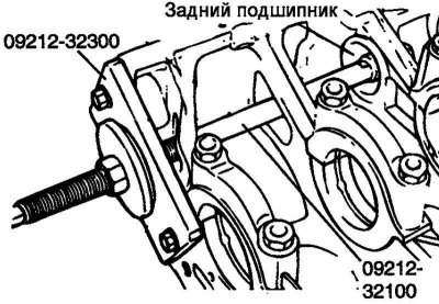
Pic. 2.99. Fixing a special tool on the front end of the block
Using the special tool, remove the left balance shaft rear bearing from the cylinder block. Fix the tool on the front end of the block (pic. 2.99).
Using the special tool, install the left balance shaft rear bearing into the cylinder block.
Note. At installation grease the bearing and its seat with engine oil.
The rear bearing of the left balance shaft does not have an oil supply hole.
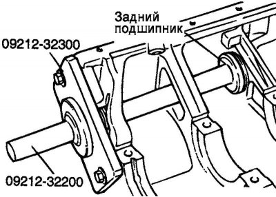
Pic. 2.100. Installing the rear bearing of the right balance shaft
Using the special tool, install the right balance shaft rear bearing into the cylinder block (pic. 2.100).
Note. At installation grease the bearing and its seat with engine oil.
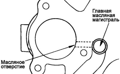
Pic. 2.101. Scheme of alignment of the oil supply hole in the bearing and block
Align the oil supply holes in the bearing and block (pic. 2.101).
Pic. 2.102. Installation diagram of the front bearing of the right balance shaft
Using the special tool, install the right balance shaft front bearing into the cylinder block (pic. 2.102).
Pic. 2.103. Scheme of alignment of the oil supply hole in the bearing and block
Note. Align the oil supply holes in the bearing and block (pic. 2.103).
Assembly
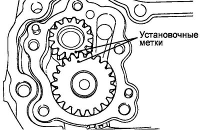
Pic. 2.104. Alignment marks of gear wheels of the oil pump
Lubricate the oil pump gears with engine oil. Install the gears in the housing, aligning the alignment marks (pic. 2.104).
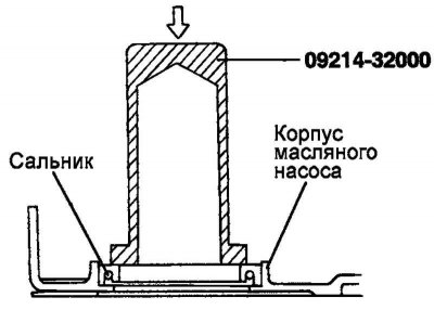
Pic. 2.105. Crankshaft Seal Fittings
With mandrel (09214-32000) install the front crankshaft oil seal into the cover (pic. 2.105).
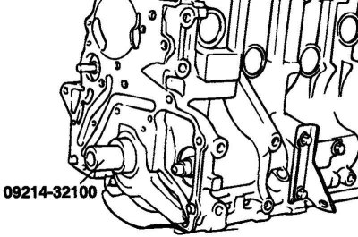
Pic. 2.106. Installation on the crankshaft of a special mandrel
Install the mandrel on the crankshaft (09214-32100). Lubricate the mandrel with engine oil (pic. 2.106).
Install a new front cover gasket. Install the front cover. Tighten the mounting bolts by hand.
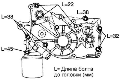
Pic. 2.107. Bolts of fastening of a forward cover
Tighten the mounting bolts to the specified torque (pic. 2.107).
The moment of an inhaling of bolts of fastening of a forward cover: 20–27 Н·м.
Insert a screwdriver into the plug hole on the left side of the unit. Check the depth of the screwdriver. If necessary, change the position of the balance shaft. Tighten the new shaft mounting bolt.
Install a new oil pump plug o-ring.
Using a special wrench, tighten the pump plug to the specified torque.
Tightening torque of the oil pump plug: 20–27 Nm.
Pic. 2.108. Sealant laying scheme
Apply a bead of sealant to the groove of the oil pan flange, as shown in Figure 2.108.
Note. The diameter of the sealant roller is approximately 4 mm.
Note. Install the pan within 15 minutes after applying the sealant.
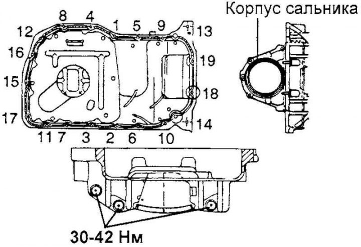
Install the upper and lower pallets, tighten the fastening bolts to the specified torque.
The moment of an inhaling of bolts of fastening of the oil pallet: 10–12 Н·м.
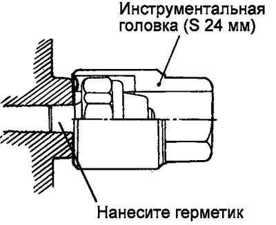
Apply sealant to the threads of the oil pressure switch. Use a 24 mm deep socket to wrap the sensor.
Sealant: Three Bond 1104 or equivalent.
Note. Do not exceed the specified tightening torque of the sensor-switch.
Tightening torque for oil pressure switch: 8–12 Nm.