
Contents: Removal ⇓ Examination ⇓ Assembly ⇓ Installing the oil pump housing seal ⇓ Checking the Oil Pressure Warning…⇓
Removal
Remove the timing belt.
Loosen the oil pan mounting bolts.
Remove the oil pan.
Remove the oil pump oil receiver.
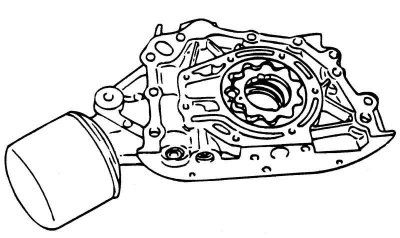
Fig. 2.187. Oil pump assembly
Remove the front cylinder block cover (oil pump housing) as an assembly (Fig. 2.187).
[The article is borrowed from an online resource: www.hyundaibook.ru]
Remove the front cylinder block cover (oil pump housing) as an assembly.
Remove the drive and driven gears from the front cylinder block cover. The drive and driven gears have alignment marks.
Examination
Check the front cylinder block cover for cracks or damage and replace it if necessary.
Check the front crankshaft oil seal for wear or damage to the working edges.
Check the oil pan for breakage, damage or cracks and replace it if necessary.
Check the oil pan for breakage, damage or cracks and replace it if necessary.
Check the contact surfaces of the oil pump housing with the pump gears for damage or wear.
Check the gear teeth for wear or damage.
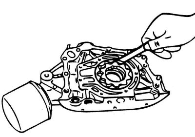
Fig. 2.188. Checking the radial clearance between the outer diameter of the driven gear and the socket in the pump body using a flat feeler gauge
Check the clearance between the outer diameter of the driven gear and the socket in the pump body (Fig. 2.188).
The radial clearance between the outer diameter of the driven gear and the socket in the pump body should be 0.120–0.185 mm.
The gap between the gear teeth should be 0.025–0.069 mm.
Clearance between the ends of the gears and the plane of the pump body, mm:
- driven gear - 0.04–0.09;
- pinion gear - 0.040–0.085.
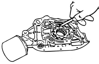
Fig. 2.189. Checking the clearance between gear teeth using a flat feeler gauge
Check the clearance between the pump gear teeth (Fig. 2.189).
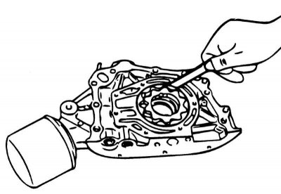
Fig. 2.190. Checking the clearance between the ends of the gears and the plane of the pump body using a flat feeler gauge
Check the clearance between the ends of the gears and the plane of the pump body (Fig. 2.190).
Check the ease of movement of the plunger of the pressure reducing valve in the seat of the pump body.
Check the pressure reducing valve spring for deformation and broken coils.
Length of pressure reducing valve spring, mm:
- in a free state - 46.6;
- under a load of 6.1 kgf - 40.1.
Assembly
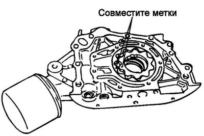
Fig. 2.191. Alignment of driving and driven gears
Install the drive and driven gears into the front cover of the cylinder block (oil pump housing), ensuring that they are correctly positioned according to the marks (Fig. 2.191).
Install the oil pump cover and tighten the mounting bolts to the specified torque. After tightening the bolts, check the smooth rotation of the pump gears.
Tightening torque of oil pump cover bolts: 8–12 N·m.
Install the plunger and spring of the relief valve, after coating the plunger with engine oil. Tighten the plug of the relief valve to the specified torque.
Tightening torque of the pressure reducing valve plug: 40–50 Nm.
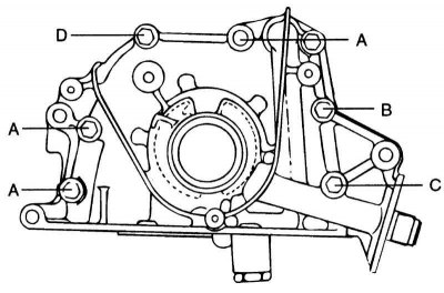
Fig. 2.192. Cylinder block front cover fastening bolts (marked with Latin letters)
Install the front cylinder block cover with a new gasket and tighten the mounting bolts (Fig. 2.192.) to the specified torque.
Tightening torque of the front cylinder block cover mounting bolts: 20–27 N·m.
Bolt length:
- A: 30 mm;
- H: 45mm;
- C: 60 mm;
- D: 22 mm.
Installing the oil pump housing seal
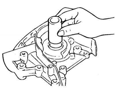
Fig. 2.193. Installing a special tool
Install the special tool (oil seal guide bushing 09214-32100) into the oil pump housing hole (Fig. 2.193).
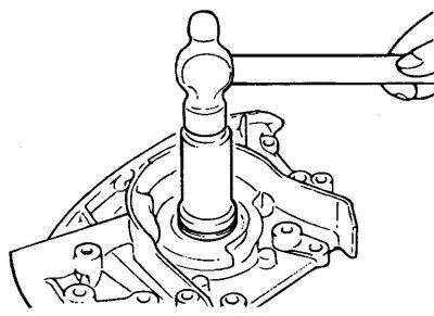
Fig. 2.194. Pressing in the front crankshaft oil seal
Press the oil seal into the hole in the front cover of the cylinder block using a mandrel (Fig. 2.194).
Install the oil receiver.
Clean both sides of the oil pan gasket and the mating surface of the cylinder block.
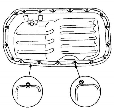
Fig. 2.195. Applying sealant to the oil pan flange
Apply sealant to the groove of the oil pan flange (Fig. 2.195).
Note: The sealant bead thickness should be approximately 4 mm.
The oil pan must be installed no later than 15 minutes after applying the sealant.
Install the oil pan and tighten its mounting bolts to the specified torque.
Tightening torque of oil pan mounting bolts: 10–12 Nm.
Checking the Oil Pressure Warning Light Sensor
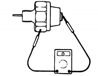
Fig. 2.196. Checking the presence of an electrical circuit between the terminal and the sensor body using an ohmmeter
Use an ohmmeter to check for an electrical circuit between the terminal and the sensor body (Fig. 2.196). If there is an open circuit, replace the sensor.
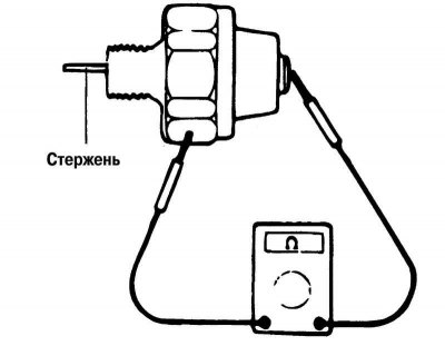
Fig. 2.197. Checking the presence of an electrical circuit between the terminal and the sensor body by pressing on the sensitive element of the sensor using an ohmmeter
Check for the presence of an electrical circuit between the terminal and the sensor body when pressing the sensor's sensitive element (Fig. 2.197). If the circuit does not open when pressing the sensitive element, replace the sensor.
Create a vacuum of 50 kPa in the sensor through the oil supply hole. If there is no electrical circuit between the output and the sensor body, the sensor is in good condition.
Make sure the sensor is tight. A leak indicates a break in the sensor diaphragm. Replace the sensor with a damaged diaphragm.