Removal
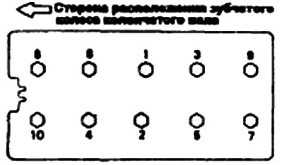
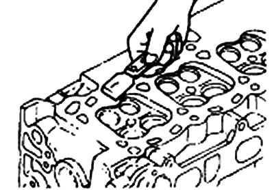
1. Using a special tool, a cylinder head bolt wrench (09221—32001), unscrew the cylinder head mounting bolts as shown in the figure.
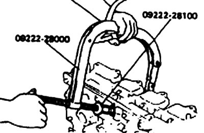
2. Using a special tool, a clamp to compress the valve springs (09222—28000, 09222— 28100), remove the cracker. Next, remove the upper valve spring plate, valve spring, lower plate and valve.
Note: Keep these parts in the same order as they need to be installed in their original locations.
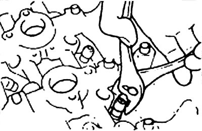
3. Use pliers to remove the sealing cap. Do not reuse it.
Examination
Cylinder head
1. Check the cylinder head for cracks, damage and coolant leakage. If cracks are present, replace the head.
2. Completely remove scale, sealant and carbon deposits. After cleaning the valves, blow them out with compressed air to ensure that they are not clogged.
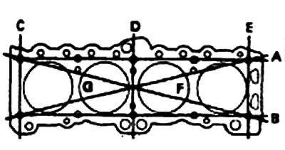
3. Check the flatness of the cylinder head joint surface using a straight edge ruler installed in directions A, B, etc. as shown in the figure. If the deviation from the plane in any direction is beyond the specified limits, replace the cylinder head or lightly treat its surface.
- Deviation from the flatness of the cylinder head surface:
- Nominal value - less than 0.05 mm
- Limit - 0.1 mm
Valves
1. Using a wire brush, thoroughly clean the valve.
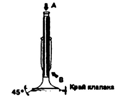
2. Check each valve for wear, damage and destruction of the head and stem in area B. Repair or correct if necessary. If end A of the stem is worn, restore its surface. Also restore the surface of the valve working chamfer. If the valve edge height is less than the permissible limit, replace the valve.
| Valve edge height | |
| Nominal size | |
| Inlet valve | 1.0 mm |
| Exhaust valve | 1.5 mm |
| Maximum size | |
| Inlet valve | 0.7 mm |
| Exhaust valve | 1.0 mm |
Valve springs
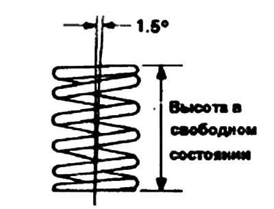
1. Check the length of the spring in the assembled state and its extension. If it exceeds the permissible limits, replace the spring.
2. Check the parallelism of the ends of each spring. If it is outside the specified limits, replace the spring.
| Valve springs | |
| Nominal value | |
| Height in free state | 48.3 mm |
| Load | 300 N/40 mm |
| Deviation from parallelism of the ends | 1.5° or less |
| Limit value | |
| Height in free state | 1 mm less |
| Deviation from parallelism | 4° |
Valve guide bushings
Check the clearance between the valve stem and the bushing.
If it exceeds the specified limits, replace it with a bushing of the following size:
Clearance between valve stem and bushing
| Nominal size | |
| Inlet valve | 0.020-0.047 mm |
| Exhaust valve | 0.050-0.085 mm |
| Maximum size | |
| Inlet valve | 0.1 mm |
| Exhaust valve | 0.15 mm |
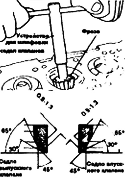
Valve seat
Check the valve seat for signs of overheating and proper contact with the valve face. Repair or replace the valve seat if necessary. Before repairing the seat, check the valve bushing for wear. If the bushing is worn, replace it, then repair the seat. Repair the valve seat using a valve seat grinder or a milling cutter. The width of the contact strip of the seat with the valve face must have a certain value, and the contact strip must be located in the center of the valve face.
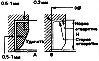
Valve seat replacement procedure
1. A valve seat worn beyond the permissible limits should be replaced at normal temperature after cutting off most of the seat wall using a valve seat grinder as shown in Fig. A.
Installation
Note:
- 1) Clean all parts before assembly.
- 2) Use motor oil to lubricate rotating and sliding parts.
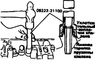
1. After installing the lower spring plate, press the sealing cap onto the valve sleeve. Press the cap on by gently rotating the valve sealing cap installer. The sealing cap is installed in the desired position with a special tool. If the sealing cap is not positioned correctly, the protrusion of its inner hole may be eccentric and oil may leak into the valve sleeve. Do not rotate the cap during installation. Do not use old sealing caps.
2. Apply engine oil to each valve. Insert the valves into the bushings, do not force the valve stem through the sealing cap. After installation, make sure the valve moves easily.
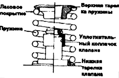
3. Install the valve springs and their upper retainers.
Valve springs should be installed with the varnished side facing the top plate.
4. Using a valve spring compressor, remove the keepers (Tools 09222-28000 and 09222-28100, see illustration). Remove the upper retainer, spring, lower retainer and valve.
Note: Keep these parts in the order they are to be installed in their places.
5. Clean those surfaces of the cylinder block and cylinder head that come into contact with the gasket installed between them.
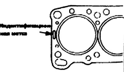
6. Install a new gasket on the cylinder head. Do not apply sealant to the gasket or use old gaskets.
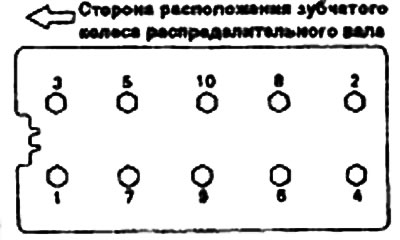
7. Using a special tool, a wrench to tighten the cylinder head mounting bolts (09221—32001), tighten the cylinder head bolts in the order shown in the figure.
- Tightening torques: Cylinder head bolts (cold engine) - 90-100 Nm