
Removal
1. Remove the timing belt.
2. Remove all oil pan bolts.
3. Remove the oil pan.
4. Remove the oil receiver and gasket.
5. Remove the plunger and gasket, then remove the spring and valve from the oil filter bracket hole.
6. Remove the oil pressure sensor.
7. Remove the oil filter bracket and gasket.
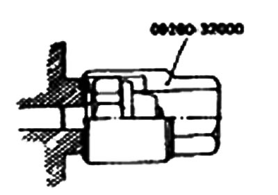
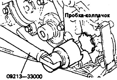
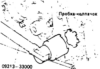
8. Using the special tool, remove the plug cap from the front cover in the oil pump area.
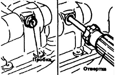
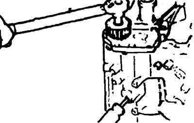
9. Remove the plug from the left side of the cylinder block and insert a screwdriver with a rod diameter of 8 mm into the opening that opens. The screwdriver rod should be inserted more than 60 mm.
10. Remove the oil pump drive gear and the left balance shaft mounting bolt.
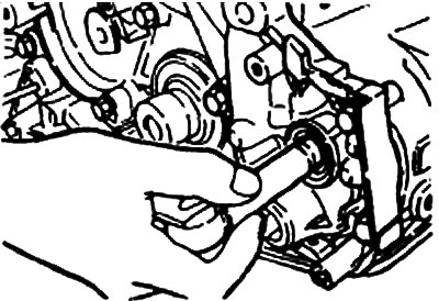
11. Remove the front cover mounting bolts and remove the front cover and gasket. Remove both balance shafts from the front cover.
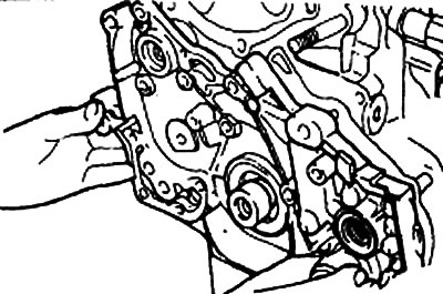
12. Remove the oil pump cover from the front cover.
13. Remove the oil pump gears from the front cover.
Examination
Front cover
1. Check if the oil passages are clogged and clean them if necessary.
2. Check the balance shaft front bearing area for wear, damage and scoring. Replace the front cover if necessary.
3. Check the front cover for cracks or other damage. Replace the front cover if it is damaged or cracked.
Balance shaft
Check the journals for wear and scoring.
If there is excessive wear or scoring, check the bearing.
If necessary, replace the balance shaft bearing or both.
Seal
1. Check the oil seal lip for wear and damage. Replace the oil seal if necessary.
2. Check the seal lip for damage. Replace it if necessary.
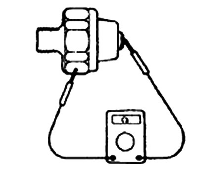
Oil pressure sensor
1. Using an ohmmeter, check the electrical conductivity between the terminal and the housing. If there is none, replace the sensor.
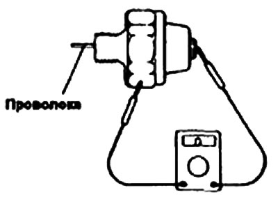
2. Check the electrical conductivity between the terminal and the housing by inserting a thin wire into the sensor hole. If there is electrical conductivity, replace the sensor.
3. If there is no electrical conductivity when creating a vacuum of 50 kPa in the oil pipe, the sensor is working normally. Make sure there is no air leak. The presence of an air leak indicates a ruptured diaphragm. Replace the sensor.
Oil pump
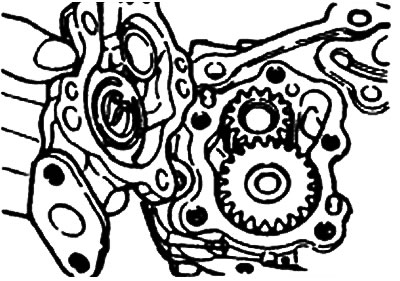
1. Install the oil pump gears and, by rotating them, check for ease of rotation and absence of play.
2. Check that there are no wear grooves on the surface of the oil pump cover and gears.
3. After installing the gears, measure the gap at the tops of the gear teeth.
The material is reprinted from another resource (HYUNDAIBOOK)
Balance shaft bearings
Replacement
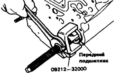
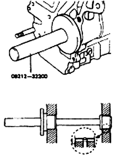
1. Using the special tool, remove the right balance shaft front bearing from the cylinder block.
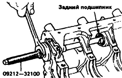
2. Using the special tool, remove the right balance shaft rear bearing from the cylinder block.
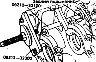
3. Using the special tool, remove the left balance shaft rear bearing from the cylinder block. At this time, install the special tool on the front surface of the cylinder block to hold the bearing puller.
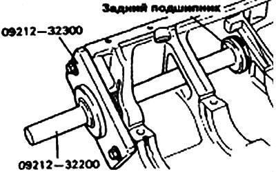
4. Using the special tool, install the left balance shaft rear bearing into the cylinder block.
Note:
- 1. Lubricate the outer surface of the rear bearing and the mounting hole in the cylinder block with engine oil.
- 2. The left rear bearing has no lubrication holes.
5. Using the special tool, install the right balance shaft rear bearing into the cylinder block.
Note:
- 1. Lubricate the outer surface of the bearing with engine oil.
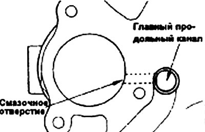
- 2. Make sure that the bearing oil hole is aligned with the cylinder block oil hole.
6. Using the special tool, install the right balance shaft front bearing into the cylinder block.
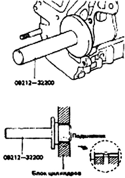
Note: Make sure that the bearing oil hole is aligned with the cylinder block oil hole.
Installation
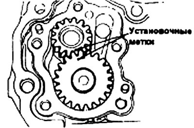
1. Apply engine oil to the gears and align the timing marks.
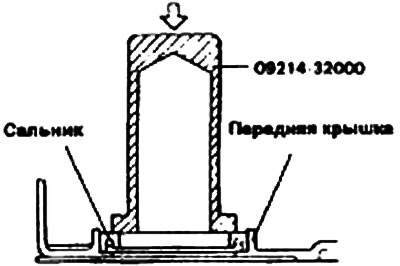
2. Using a special tool, a device for installing the front crankshaft oil seal (09214-32000), install the front crankshaft oil seal into the front cover.
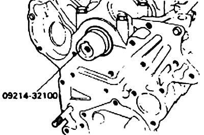
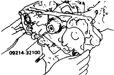
3. Install special tools (09214-32100) onto the front end of the crankshaft and apply a thin layer of engine oil to the outside surface of the front cover installation tool.
4. Install the front cover on the new gasket and temporarily tighten the mounting bolts (except the oil filter bracket mounting bolts).
5. Install the front cover on the new gasket and tighten the bolts to the specified torque.
Front cover:
- Tightening torque:
- * 27—34 Nm
- 20—27 Nm
- All except oil pump bracket mounting bolts - 15-22 Nm
6. Insert a screwdriver through the plug hole on the left side of the cylinder block to hold the shaft in a certain position and then tighten the nut.
7. Install the new O-ring into the groove of the front cover and tighten it to the specified torque.
8. Using the special tool, install the plug cap and tighten it to the required torque.
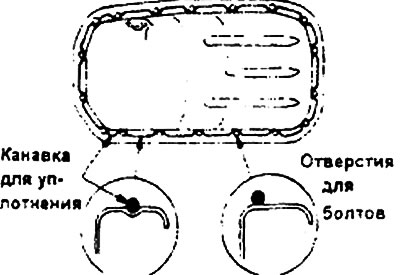
9. Apply the seal into the groove of the oil pan flange as shown in the figure.
Note:
- 1) Apply a sealant thickness of approximately 4mm.
- 2) After applying the seal, install the oil pan within 15 minutes.
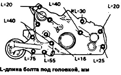
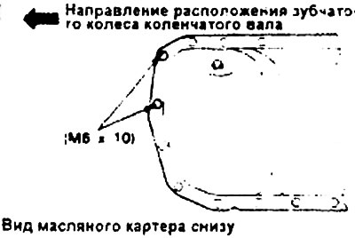
10. Note the difference in bolt length in the arrangement shown. Install the oil pan and tighten the bolts to the specified torque.
- Tightening torque: Oil pan mounting bolts - 6-8 Nm
11. Using a special tool, install the oil pressure sensor after applying a sealing compound to its threaded portion.
- Sealing compound - Threebond 1104 or equivalent
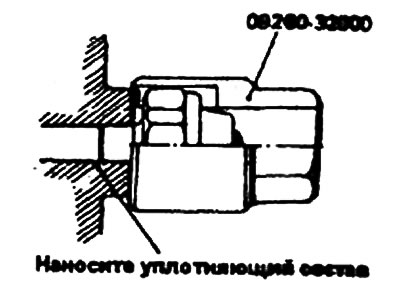
Note: Do not tighten the oil pressure sensor too much.
- Tightening torque: Oil pressure sensor - 8-12 Nm