Removal
Connecting rod lower head cover
Note: Keep the bearing shells in connecting rod numbering order (corresponding to cylinder numbering) for later installation.
1. Loosen the connecting rod lower head cover nuts and remove the cover and lower bearing shell.
2. Slide each connecting rod to the top of the cylinder.
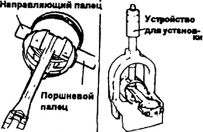
The procedure for removing and installing the piston pin
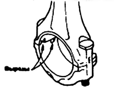
1. Use special tools (09234-32001) for disassembling and assembling the piston and connecting rod.
2. Install the appropriate insert into the fork of the tool. Position the insert between the connecting rod and the piston.
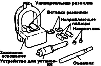
3. Insert the appropriate puller into the tool arch hole.
Note: Position the piston, connecting rod and piston pin assembly along the puller axis.
4. Press the piston pin out of the upper connecting rod head.
5. Insert the appropriate guide pin through the piston into the small end of the connecting rod. Insert the guide pin from the opposite side of the piston.
Note: The guide pin centers the connecting rod in the piston. When the piston, connecting rod, piston pin, and guide pin are positioned in the fork of the tool, the guide pin centers the entire assembly in the tool. If too small a guide pin is used, the piston assembly cannot be centered in the tool, which may result in damage to the fork or the insert of the tool.
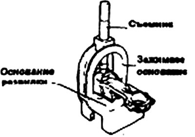
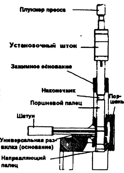
6. Install the piston assembly into the fork of the device. The device will support the connecting rod on the piston pin. Move the piston into the fork until the guide pin stops against the insert.
7. Adjust the setting rod to the appropriate length by rotating the numbered sleeve on the lettered shaft until the alphanumeric value specified in the application diagram is obtained. Turn the nut with the nozzle to lock the numbered sleeve on the shaft.
8. Insert the installation rod into the hole in the device arch. Press the piston pin into the connecting rod head until the bushing of the installation rod touches the top of the device arch. The guide pin will fall out of the connecting rod head when the piston pin is pressed in.
Examination
Piston and piston pin
1. Check each piston for abrasion, scoring, wear and other defects. Replace any defective pistons.
2. Check each piston ring for damage or excessive wear. Replace any defective rings.
3. Check the fit of the piston pin in the piston boss holes. Replace all defective pistons and piston pins. The piston pin should fit smoothly into the piston boss holes by hand at room temperature.
Piston rings
1. Check the side clearance of the piston rings. If the measured value exceeds the permissible value, insert a new ring into the piston groove and measure the side clearance. If the clearance still exceeds the permissible value, replace the piston and piston rings. If in this case the clearance does not exceed the permissible value, replace only the piston rings.
- Nominal value:
- Lateral clearance of piston rings - 0.03-0.07 mm
- Limit value - 0.1 mm
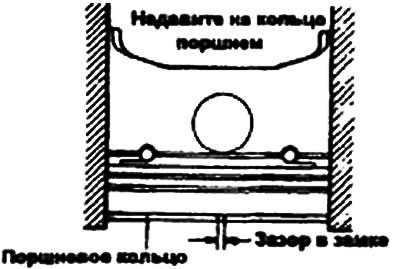
2. To measure the gap in the piston ring lock, insert the rings into the cylinder. Set the ring in a plane perpendicular to the cylinder wall, pressing lightly on the ring with the piston. Measure the gap with a feeler gauge. If the gap exceeds the permissible limits, replace the piston ring.
Piston ring gap
- Nominal value
- Ring No.1 - 0.25-0.45 mm
- Ring No.2 - 0.35-0.50 mm
- Oil scraper ring - 0.20-0.70 mm
- Limit value
- Rings No.1, No.2 - 0.8 mm
- Oil scraper ring - 1.0 mm
Connecting rods
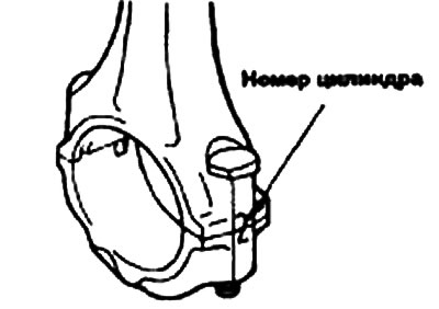
1. When installing the connecting rod cap, make sure that the cylinder numbers on the connecting rod and cap match. When installing a new connecting rod, make sure that the bearing retaining cutouts are on the same side.
2. Replace the connecting rod if there is damage to the pressure-bearing surfaces of the upper and lower heads, or if there is stepped wear or if the inner surface of the upper head bore is highly rough.
Installation
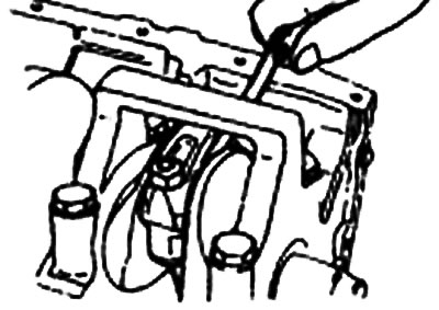
1. Install the spacer ring.
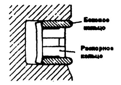
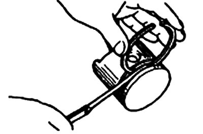
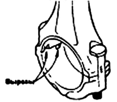
2. Install the upper side ring. To install it, insert one end of it between the wall of the piston ring groove and the spacer ring, press it to the bottom of the groove and, pressing with your finger as shown in the figure, insert the upper side ring into the groove.
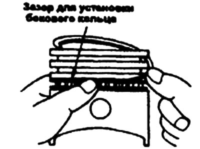
Note: Do not use a piston ring expander when installing the side rings.
3. Install the lower side ring in the same way.
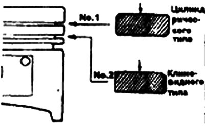
4. Using a piston ring expander, install piston ring No.2.
5. Install piston ring No.1.
6. Apply engine oil to the outer surfaces of the piston and piston rings.
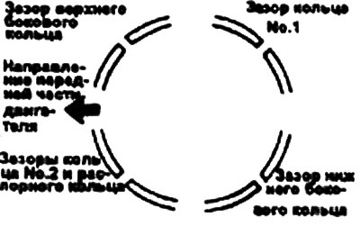
7. Arrange the piston rings so that the gaps in the joints of adjacent piston rings are as far apart as possible. Make sure that these gaps are not located in the directions of the piston pin axis and load bearing.
8. When installing the piston into the cylinder, press the rings into the piston grooves using a crimping tool.
9. Make sure that the mark marking the front of the piston and the mark marking the front of the connecting rod (identification mark) are facing toward the front of the engine.
10. When installing the connecting rod lower head cover, make sure that the marks corresponding to the cylinder number on the connecting rod and cover match.
11. When installing a new connecting rod, make sure that the cutouts for retaining the bearing shells are located on the same side.
12. Tighten the connecting rod lower head cover fastening nuts.
- Tightening torque: Connecting rod lower head cover fastening nuts - 50-53 Nm.
13. Check the connecting rod side clearance.
- Lateral clearance - 0.10-0.25 mm
- Maximum clearance - 0.4 mm