Disassembly
1. Remove the timing belt sprockets, front cover, flywheel, flywheel cylindrical rim and oil pan.
2. Remove the rear plate and rear oil seal.
3. Remove the lower connecting rod head caps.
- Nominal value: Outer diameter of crankshaft main journal - 56.995 mm.
Note: Mark the crankshaft main bearing caps to ensure they are installed in the correct positions.
4. Remove the main bearing caps and crankshaft.
Examination
Crankshaft
1. Check the crankshaft main and connecting rod journals for damage, uneven wear, cracks. Check if they are clogged lubrication holes. Correct or replace any defective parts.
2. Check the out-of-roundness and taper of the main and connecting rod journals of the crankshaft.
Nominal value:
- The outer diameter of the crankshaft main journal is 56.995 mm
- The outer diameter of the crankshaft connecting rod journal is 44.980-44.995 mm
Main and connecting rod bearings
Visually inspect each bearing for delamination, melted areas, scoring, and improper contact. Replace defective bearings.
Measuring oil clearances
Check the oil clearance by measuring the outside diameter of the crankshaft main and connecting rod journals and the inside diameter of the bearings. The clearance is obtained by calculating the difference between the measured outside and inside diameters.
Nominal value:
Oil clearance:
- Crankshaft main bearings - 0.02-0.05 mm
- Connecting rod bearings - 0.02-0.05 mm
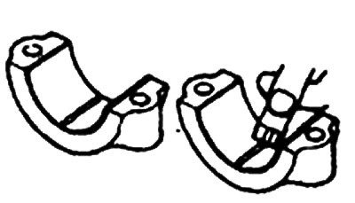
Plastic template method
A plastic template can be used to measure the gap.
1. Remove oil, grease and dirt from the bearings and crankshaft journals.
2. Cut a piece of plastic template to a length equal to the width of the bearing and place it along the axis of the journal away from the lubrication holes.
3. Install the crankshaft, bearing shells and caps and tighten them to the specified torque. Do not rotate the crankshaft during this operation.
Remove the bearing caps. Using the scale printed on the plastic template package, measure the thickness of the plastic template at its widest point.
If the gap exceeds the repair tolerance, the bearing must be replaced or a smaller bearing must be used.
When installing a new crankshaft, use the nominal size bearings. If the nominal clearance cannot be obtained even after replacing the bearings, grind the main and connecting rod journals to a smaller size and install bearings of the appropriate size.
Seals
Check the front and rear bearing shells for damage and wear on the working edge. Replace a defective seal.
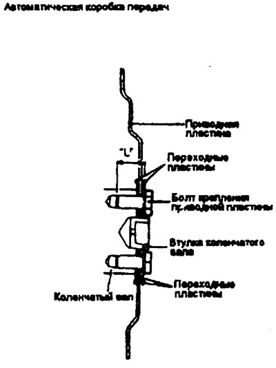
Adapter plate
Replace a warped, damaged or cracked adapter plate.
Installation
Main bearings
1. Install the main bearing with the groove into the cylinder block bed.
2. Install the main bearing without the groove.
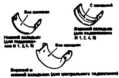
3. The upper and lower center bearing shells do not have grooves.
4. Install the crankshaft. Apply engine oil to its journals.
5. The covers should be installed with the arrow pointing towards the front of the engine. The cover numbers should match the cylinder numbers.
6. Tighten the cover mounting bolts to the specified torque in the following sequence: center, No.1, No.2, front and rear.
- Tightening torque: Main bearing cap bolts - 50-55 Nm
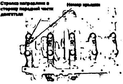
7. Before tightening to the required torque, the cover bolts should be tightened evenly in 4-5 steps.
8. Make sure that the crankshaft rotates freely and has adequate axial clearance.
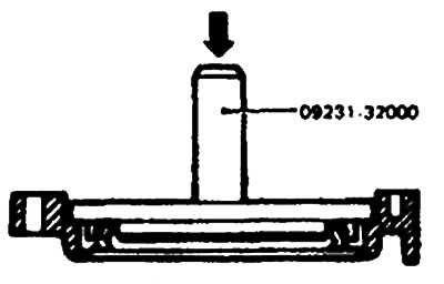
9. Using a special tool (09231-32000), install the seal into its housing.
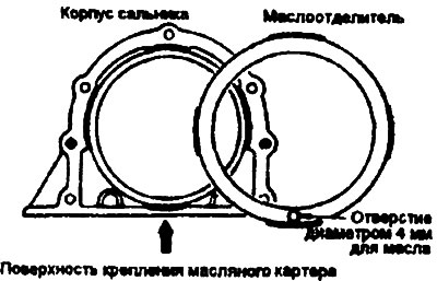
10. Install the oil separator into the housing so that the 4 mm diameter oil hole is facing downwards (towards the mounting surface of the oil pan).
11. Install the new seal housing gasket and seal housing.
12. Attach the rear plate to the cylinder block.
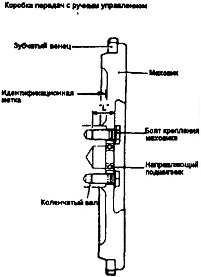
13. Install the flywheel and tighten the bolts to the specified torque.
Check the clutch mounting surface for wear.
- Wear - Max. 0.1 mm
- Tightening torques Flywheel bolts - 130-140 Nm
14. When using an automatic transmission, install the adapter and drive plates and tighten the bolts to the specified torque.
- Tightening torque: Drive plate mounting bolts - 130-140 Nm.