
Piston and connecting rod
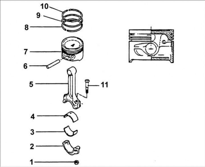
1 – bolt, 32–35 Nm; 2 – connecting rod cover; 3 – lower connecting rod bearing shell; 4 – upper connecting rod bearing shell; 5 – connecting rod; 6 – piston pin; 7 – piston; 8 – oil scraper ring; 9 – compression ring No.2; 10 – compression ring No.1; 11 – bolt.
Removal
Warning: Keep the connecting rod caps with the corresponding connecting rods for proper reinstallation into the engine cylinders.
1. Loosen the nuts and remove the connecting rod cap and the lower connecting rod bearing shell. To protect the crankshaft journals, place sections of rubber or plastic tube on the connecting rod cap mounting bolts.
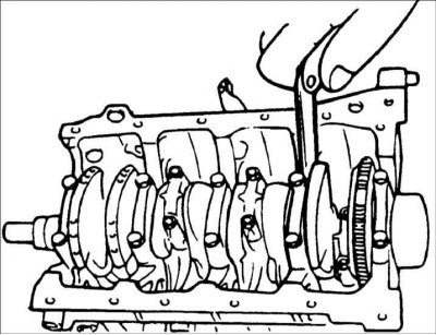
2. Use a wooden block or a hammer handle to push the piston and connecting rod out of the cylinder.
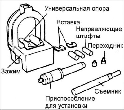
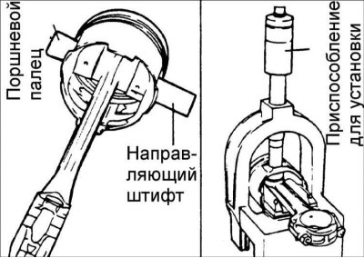
3. To disassemble and reassemble the piston and connecting rod, use special tools 09234–33001.
4. Install the universal supports into the clamp between the connecting rod and the piston.
5. Insert the puller through the hole in the clamp arch.
Warning! Insert the clamp with the piston, connecting rod and puller under the press slide.
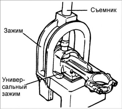
6. Use a puller to push the piston pin out of the piston.
Examination
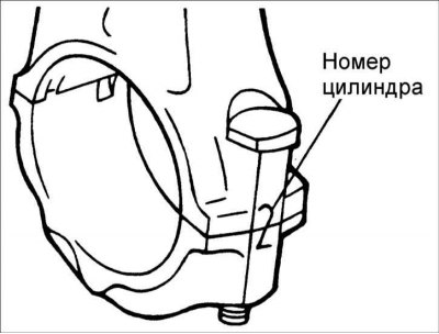
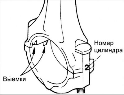
1. When installing, make sure that the connecting rod and connecting rod cap match the cylinder number they are being installed in. When installing a new connecting rod, make sure that the marks that determine its position are on the same side as the marks on the other connecting rods.
2. Replace the connecting rod if there is damage on both bearing surfaces. Also replace the connecting rod if there is wear or damage on the surface mating with the piston pin.
3. Check the bend of each connecting rod. If necessary, replace the connecting rods. Replace the connecting rod together with the connecting rod cap.
- Allowable bending of connecting rod: 0.05 mm/ 100 mm length
- Permissible twisting of the connecting rod: 0.1 mm / 100 mm length
Installation
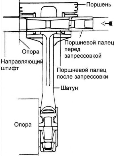
1. Install the guide pins through the piston into the connecting rod and install the piston pin on the other side of the piston.
Warning! The guide pins determine the position of the connecting rod in the piston. After installing the piston, connecting rod, piston pin and piston pin installation tool into the inserts, the guide pins also determine their position in the clamp.
2. The guide pins determine the position of the connecting rod in the piston. After installing the piston, connecting rod, piston pin and piston pin installation tool into the inserts, the guide pins also determine their position in the clamp.
3. Check the correct relative position of the piston and connecting rod and, by turning the knurled nut, secure the numbered sleeve on the shaft.
4. Insert the shaft through the hole in the clamp arch. Press the piston pin into the connecting rod until the bushing on the shaft contacts the top of the clamp arch, and the guide pin should fall out of the piston.
Warning! The piston pin pressing force must not exceed 22,500 N.
Pressing depth: 0.3–0.5 mm
5. Make sure the piston and connecting rod marks are facing the front of the engine.
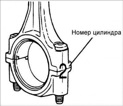
6. After installing the connecting rod caps, check that the cylinder number on the connecting rod and cap matches the cylinder number.
7. When installing a new connecting rod, make sure the bearing support recesses are on the same side as the other connecting rods.
8. Tighten the connecting rod cap union nuts.
Tightening torque: 32–35 Nm
9. Using a feeler gauge inserted between the connecting rod and the crankshaft, measure the connecting rod side clearance.
- Nominal connecting rod side clearance: 0.10–0.25 mm
- Maximum clearance: 0.40 mm