


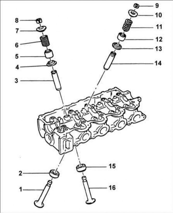
1 – exhaust valve; 2 – exhaust valve seat; 3 – valve guide bushing; 4 – valve spring plate; 5 – oil deflector cap; 6 – valve spring; 7 – valve spring holder; 8 – crackers; 9 – crackers; 10 – valve spring holder; 11 – valve spring; 12 – oil deflector cap; 13 – valve spring plate; 14 – valve guide bushing; 15 – inlet valve seat; 16 – inlet valve.
Removal
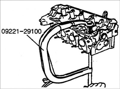
1. Using special tool 09221-29100, compress the valve spring and remove the cotters from the valve stem. Slowly release the spring compressor and remove the valve spring, spring retainer and valve from the cylinder head.
Warning: Have numbered plastic bags or containers available for storing valves.
2. Remove the oil deflector cap using pliers 09222-29000.
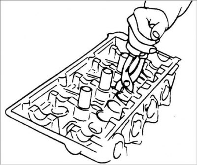
Warning: Do not reuse the valve stem seal.
Examination
Valves
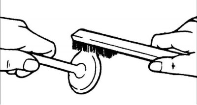
1. Use a wire brush to clean the valve.
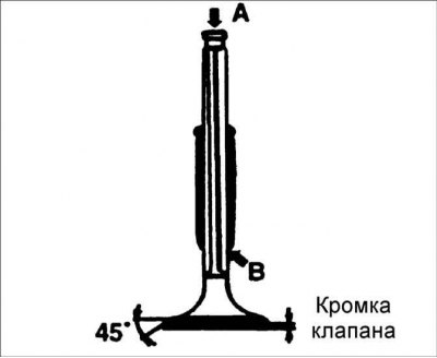
2. Inspect each valve for the following defects:
- damage or deformation of the valve stem;
- valve plate damage;
- damage or uneven wear on the end of the valve stem.
If necessary, repair or replace the valve.
Edge thickness:
- Intake valves: 1.1 mm
- Exhaust valves: 1.3 mm
Maximum edge thickness:
- Inlet valves: 0.8 mm
- Exhaust valves: 1.0 mm
Valve spring
1. Inspect each valve spring for cracks or damage.
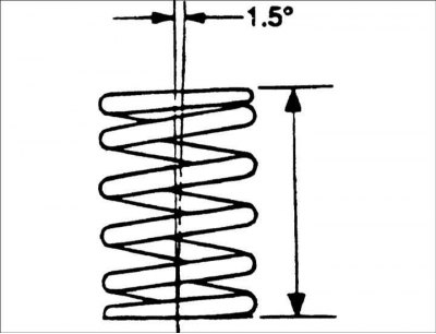
2. Measure the length of the spring in a free state. Place the spring on a flat horizontal surface and measure the deviation of the upper part of the spring from the vertical plane.
- Spring length under 21.6 kg load: 35 mm
- Spring length under 45.1 kg load: 25.2 mm
- Maximum permissible deviation of the spring from the vertical plane: no more than 1.5°
Valve guide bushings
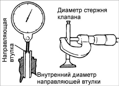
Check the clearance between the stem and the valve guide. If the clearance exceeds the maximum permissible value, replace the valve guide with a bushing of an increased repair size.
Clearance between valve stem and valve guide:
- Intake valves: 0.03–0.06 mm
- Exhaust valves: 0.035–0.065 mm
Maximum permissible clearance between the valve stem and the valve guide bushing:
- Inlet valves: 0.1 mm
- Exhaust valves: 0.15 mm
Increased valve guide dimensions
Size increase, mm | Size mark | Cylinder head hole diameter, mm |
0,05 | 5 | 11,05–11,068 |
0,25 | 25 | 11,25–11,268 |
0,35 | 50 | 11,50–11,518 |
Valve seat
Check the condition and width of the valve seat lip. Repair or replace the valve seat if necessary.
Before replacing or repairing the valve seat, check the valve guide for wear. If the valve guide is worn, replace it.
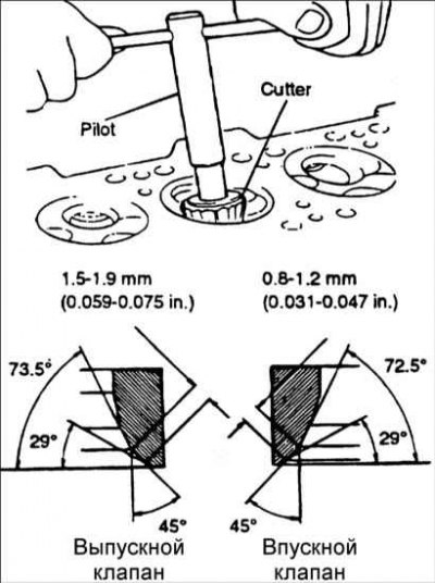
Repair of the valve seat must be carried out with an emery wheel or a milling cutter. The width of the working chamfer of the valve seat must be within the technical requirements.
Installation
Warning: Clean all parts before installation.
Warning: Apply a thin layer of engine oil to all sliding surfaces.
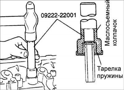
1. Using special tool 09222-22001, install the oil seal.
2. Lubricate the valve stem with engine oil and install the valve. When installing the valve, do not apply too much force to avoid damaging the valve stem seal.
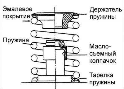
3. Install the springs and spring retainers. The springs must be installed with the enamel side facing the spring retainers.
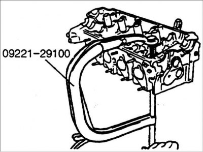
4. Use a special tool to compress the spring. Install the crackers and remove the special tool to compress the spring.
5. Install the cylinder head.