
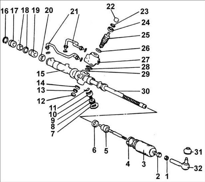
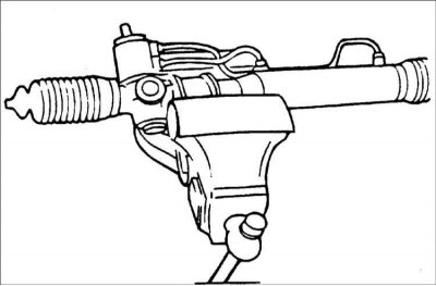
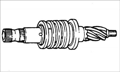
1 – tie rod end locknut, 50–55 Nm; 2 – clamp; 3 – protective cover; 4 – clamp; 5 – steering rod, 80–100 Nm; 6 – lock washer; 7 – lock nut, 50–70 Nm; 8 – cork; 9 – spring; 10 – emphasis; 11 – bushing; 12 – cork; 13 – lock nut, 20–30 Nm; 14 – ball bearing; 15 – steering gear housing; 16 – clamp; 17 – toothed rack stopper; 18 – toothed rack bushings; 19 – sealing ring; 20 – lock washer; 21 – tubes, 12–18 Nm; 22 – sealing ring; 23 – sealing ring; 24 – ball bearing; 25 – gear shaft and gear; 26 – sealing ring; 27 – control valve body; 28 - O-ring round section; 29 – needle bearing; 30 – toothed rack; 31 – dust cover; 32 – steering rod end.
Removal
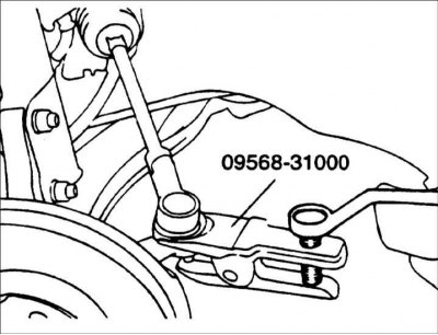
1. Remove the cotter pins and unscrew the nuts securing the ball joint pins of the steering rod ends to the steering knuckles. Use puller 09568–31000 to push the ball joint pins of the steering rod ends off the steering knuckles.
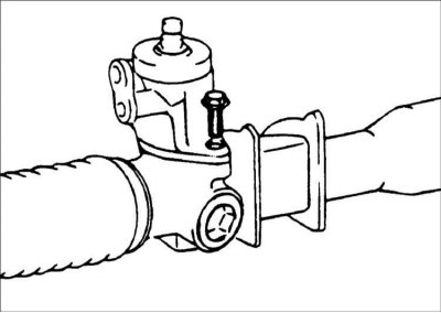
2. Remove the bolt connecting the universal joint and the steering gear shaft.
3. Drain the fluid from the power steering hydraulic drive.
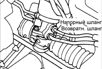
4. Disconnect the pressure and return hoses from the steering gear housing.
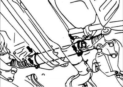
5. Remove the steering gear housing mounting bolts.
6. Remove the rear engine mount.
7. Remove the anti-roll bar.
8. Move the steering gear and remove it from the right side of the car.
Warning: When removing the steering gear, be careful not to damage the protective boots.
Checking and preliminary adjustment before installation
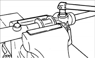
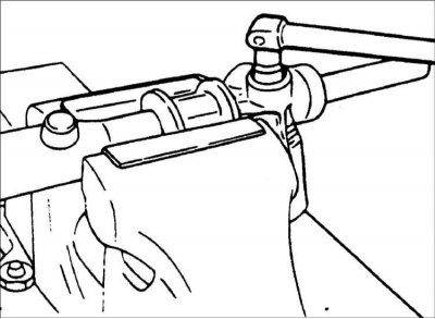
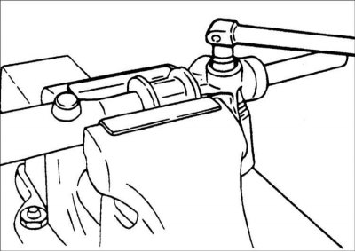
Secure the steering gear in a vice with jaws covered with soft material.
Warning: When securing the steering gear in a vice, wrap the steering gear in a cloth and be careful not to damage it when the vice is tightened.
Gear preload
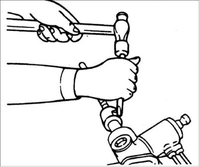
1. Measure the preload by rotating the pinion with the special tool 09565-11100 one revolution every 4-6 s. Also measure the starting force of the toothed rack.
Total gear preload: 0.6–1.3 Nm.
Warning: Measure the preload on the full stroke of the steering gear pinion.
2. If the preload is not within the required value, first adjust the tightening torque of the plug and recheck the gear preload.

3. If adjusting the plug tightening torque does not produce positive results, check or replace the plug components.
Steering traction resistance
1. Perform 10 steering rod deflections.
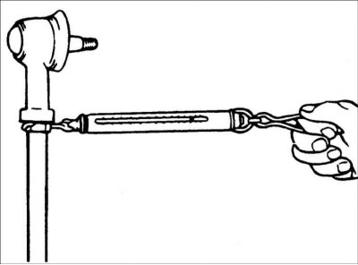
2. Use a dynamometer to measure the force required to move the steering rod.
Steering rod deflection force: 2–5 N
3. If the measured value exceeds the standard value, replace the tie rod assembly.
Warning! If the measured value is below the standard value and the steering rod turns smoothly and without play, it can be installed on the vehicle. However, if the measured value is below 4.3 N, replace the steering rod.
Checking the corrugated protective cover
1. Visually inspect the corrugated protective cover for damage and deterioration of its properties.
2. Make sure the protective cover is installed in the correct position.
3. If the corrugated protective cover is defective, replace it.
Disassembly
1. Remove the tie rod end from the tie rod.
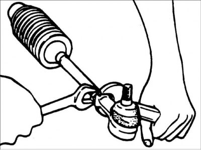
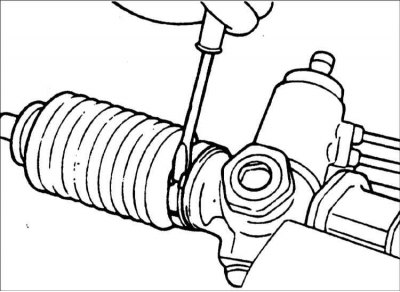
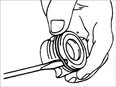
2. Using a screwdriver blade, remove the protective cover from the ball joint of the tie rod end.
3. Remove the clamp securing the corrugated protective cover.
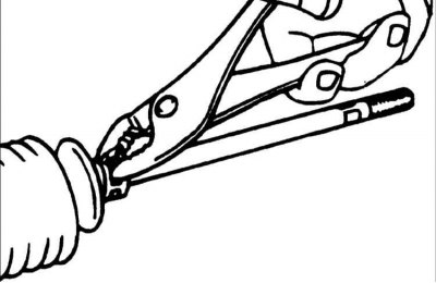
4. Remove the corrugated protective cover fastening clamp.
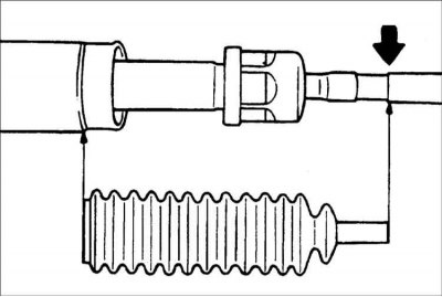
5. Move the bellows cover to the steering rod.
Warning: When replacing the bellows, check the steering gear for rust.
6. Remove the guide tube from the gear housing.
7. While slowly moving the toothed rack, drain the fluid from the steering gear housing.
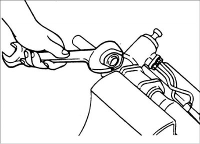
8. Unscrew the plug.
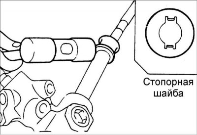
9. With the pinion turned clockwise until the rack locks, loosen the self-locking nut.
10. Use a chisel to bend back the lock washer located between the steering rod and the toothed rack.
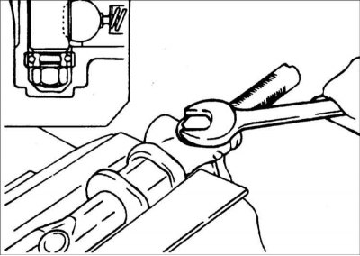
11. Unscrew the steering rod from the toothed rack.
Warning: When removing the steering rod, be careful not to turn the toothed rack.
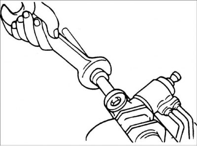
12. Unscrew the lock nut securing the plug.
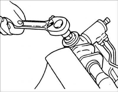
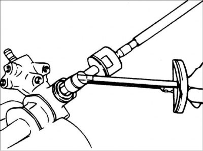
13. Using special tool 09565–21100, remove the plug.
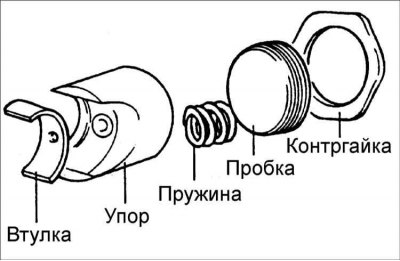
14. Remove the spring, stop and bushing from the steering gear housing.
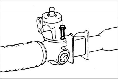
15. Remove the two bolts and remove the valve body.
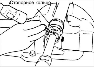
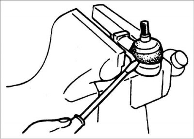
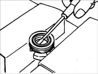
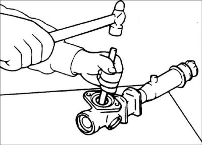
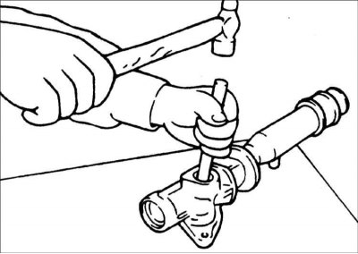
16. Using a screwdriver blade, turn the rack stopper clockwise until the end of the locking ring comes out of the groove in the steering gear housing.
17. When the end of the snap ring comes out of the hole in the rack cylinder housing, use a screwdriver blade to turn the steering gear stopper counterclockwise and remove the snap ring.
18. Remove the rack stopper, bushing and rack from the steering gear housing by moving them towards the pinion.
Warning: After removing the steering gear, make sure to replace the side housing seal ring.
19. Remove the O-ring from the rack bushing.
20. Remove the sealing ring from the rack bushing.
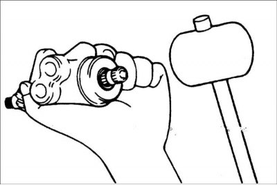
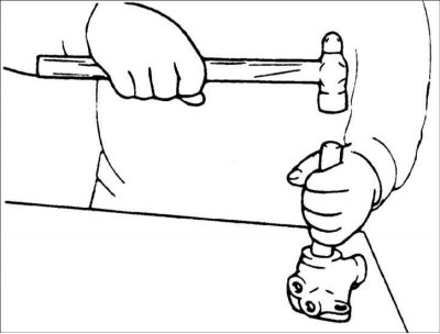
21. Use a plastic hammer to remove the valve body from its housing.
22. Using special tool 09565-21000, remove the oil seal and ball bearing from the valve body.
23. Remove the ball bearing from the gear housing.
Warning: Be careful not to damage the valve cylinder in the steering gear housing.
24. Remove the needle bearing from the steering gear housing.
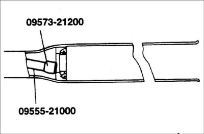
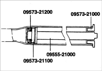
25. Using special tools 09573–21200, 09555–21000, remove the return washer and oil seal from the steering gear housing.
Warning: Be careful not to damage the rack cylinder in the pinion housing.
Checking the toothed rack
1. Check the rack for damaged or worn teeth.
2. Check the oil seal contact surfaces for damage.
3. Check the rack for deflection or twisting.
4. Check the O-ring for damage or wear.
5. Check the oil seal for damage or wear.
Checking the valve gear
1. Check the valve gear for damage to the teeth or wear.
2. Check the oil seal contact surfaces for damage.
3. Check the O-ring for damage or wear.
4. Check the oil seal for damage or wear.
Checking the bearing
1. Check the bearing for seizure or extraneous noise when it rotates.
2. Check the bearing for excessive play.
3. Check for missing needle bearing.
Other checks
1. Check the steering gear housing cylinder surface for damage.
2. Check the protective cover for damage, aging and cracks.
Assembly
1. Lubricate the sliding surface of the rack oil seal.
Recommended Lubricant: Power Steering Fluid Type 3
2. Install the return washer and oil seal into the steering gear housing in the position shown in the illustration.
3. Apply grease to the entire surface of the needle bearing.
Recommended grease: SAE J310, NLGI No.2
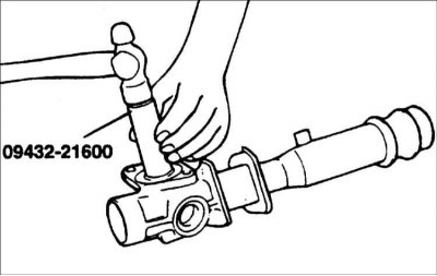
4. Secure the needle bearing to special tool 09432–21600 and install it into the steering gear housing until the tool touches the housing.
Warning: Pay attention to the installation direction of the needle bearing.
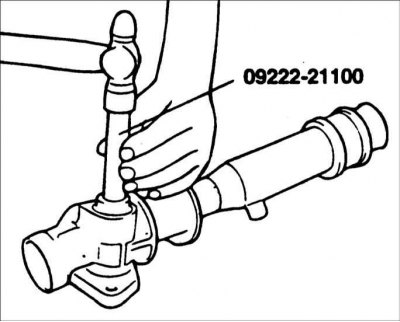
5. Lubricate the ball bearing and install it using special tool 09222–21100.
Recommended grease: SAE J310, NLGI No.2
Warning: Always use a new bearing.
6. Lubricate the oil seal surfaces of the rack bushing.
Recommended Lubricant: Power Steering Fluid Type 3
7. Install the oil seal into the rack bushing.
8. Lubricate the O-ring and install it into the rack bushing.
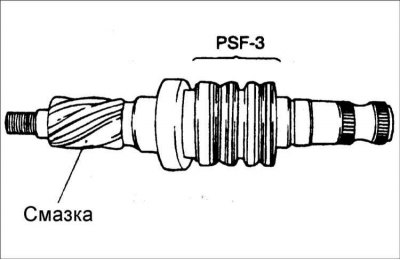
9. Lubricate the teeth of the rack and wrap it with tape.
Recommended grease: SAE J310, NLGI No.2
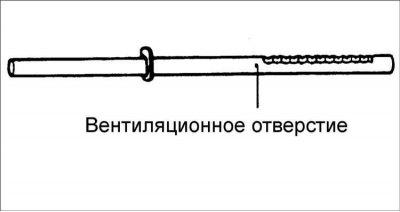
Warning: Do not block the ventilation hole in the rack with grease.
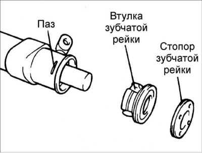
10. Install the toothed rack into the steering gear housing. Then install the bushing and the toothed rack stopper.
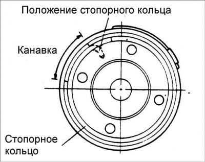
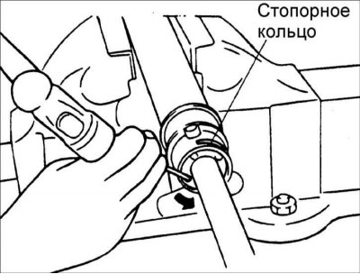
11. Press the rack stopper until a groove appears and, turning the stopper, install the retaining ring.
Warning! The retaining ring must not be visible through the hole in the rack housing.
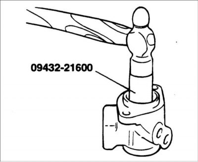
12. Using special tool 09432–21600, install the oil seal and ball bearing into the valve body.
13. Lubricate the valve assembly with oil and recommended lubricant and install it into the steering gear housing.
- Recommended oil: PSF–3
- Recommended grease: SAE J310, NLGI No.2
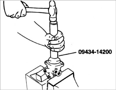
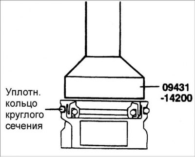
14. Lubricate with oil and install the seal into the valve body using special tool 09434–14200.
15. Install the valve body assembly with the O-ring into the steering gear housing.
16. Install the lock washer and steering rod and countersink the washer flange in two places.
Caution: Align the tabs on the lock washer with the recesses on the steering gear housing.
Warning: Always use a new lock washer.
17. With the gear turned fully clockwise, tighten the self-locking nut.
18. Apply sealant to the threaded portion of the plug and tighten the plug to the specified torque.
Tightening torque: 50–70 Nm
19. Pin the plug in two places around its circumference.

20. Install the bushing, stop and spring in the order shown in the figure. Apply sealant to the threaded part of the plug before installation.
21. Set the rack to the central position and install the cover on the steering gear housing. Using special tool 09565–21100, tighten the cover to a tightening torque of 20–25 N·m. Loosen the cover by 10° and tighten the lock nut to the specified tightening torque.
22. Tighten the guide tube to the required tightening torque and install the rubber element with glue.
Tightening torque: 50–70 Nm
23. Apply grease to the bellows boot and install it into the groove of the steering rod.
24. Secure the corrugated protective cover with a clamp.
Warning: A new clamp and clip must be used to secure the bellows cover.
25. Check that the corrugated protective cover is not twisted.
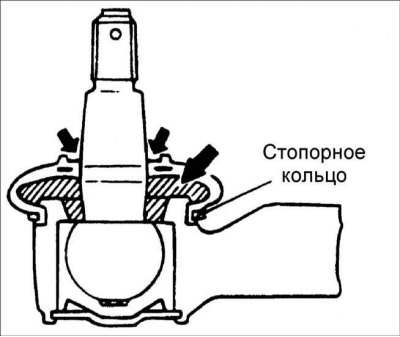
26. Fill the protective boot with lubricant, install it on the ball joint of the tie rod end and secure it with a snap ring.
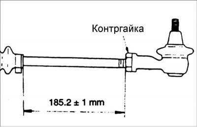
27. Install the steering rods so that the length of the left and right steering rods is the same.
Length of steering rods: 185.2±1 mm
28. Check the gear preload.
Installation
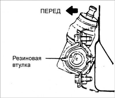
1. Install the steering gear rubber mount so that it aligns with the holes in the clamp and steering gear bracket.
2. Apply glue to the side of the cylinder where the rubber support is installed so that its split part does not open.
3. Check for fluid leaks.
4. Check that the steering wheel turns smoothly.
5. Adjust the front wheel alignment.
6. Install the remaining parts taking into account the required tightening torques.