
Elements of the air conditioning system
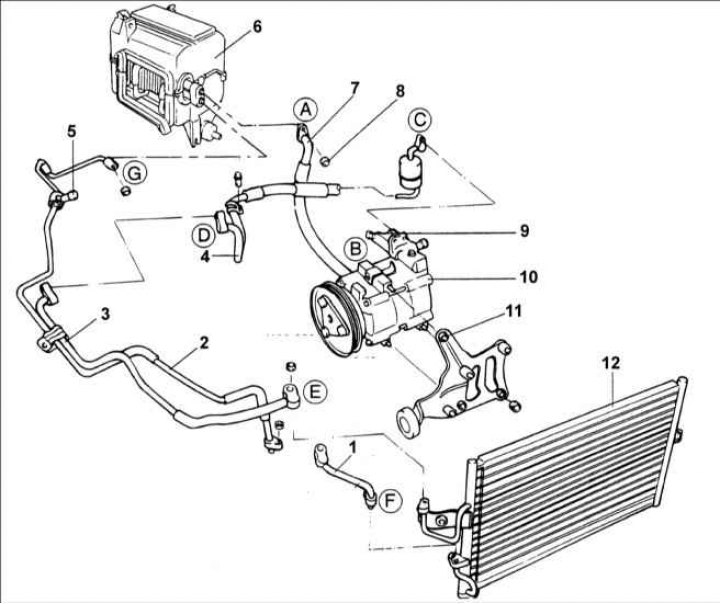
1 - tube (A); 2 - tube (IN); 3 - outlet tube; 4 - outlet tube; 5 - port from the high pressure side; 6 – evaporator block; 7 - tube; 8 - nut, 5–7 Nm; 9 - port from the low pressure side; 10 - compressor; 11 - compressor bracket; 12 - capacitor; A - evaporator to the suction tube, 5–7 Nm; B - suction pipe to the compressor, 8–12 Nm; C - compressor discharge hose, 17–26 Nm; D - discharge hose to the exhaust pipe, 19–28 Nm; E - exhaust pipe to the condenser, 19–28 Nm; F-tube (A) to the condenser, 7–11 Nm; G - tube (IN) to the evaporator, 12–15 Nm.
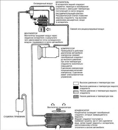
Air conditioning circuit
Order of execution
1. Install a pressure gauge on the line.
2. Start the engine, let it run at 2000 rpm-1 and set it to maximum cooling at high fan speed.
3. Open all windows or doors.
4. Install the thermometer in the air intake grille of the car.
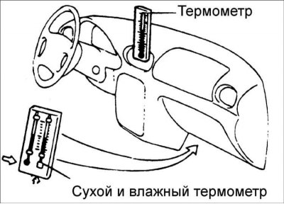
5. Install wet and dry bulbs as close as possible to the inlet of the cooling unit.
6. Check that the pressure shown on the pressure gauge is between 1.373-1.575 kPa. If the pressure is too high, pour water over the condenser. If the pressure is too low, close the front side of the condenser.
7. Check that the temperature of the air in the car's air supply grille is between 25-35°C.
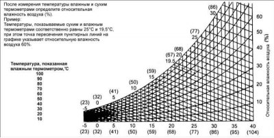
8. From the graph, calculate the relative humidity of the air by comparing the temperature of the wet and dry bulbs.
9. Measure the temperature at the car's air intake grille and calculate the difference between the dry bulb bulb and the air intake grille thermometer.
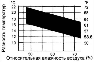
10. Check that if the intersection of relative humidity and temperature difference is within tolerance, then the air conditioning system is working properly.