
Warnings:
- Do not reuse gaskets, seals and rubber parts. Replace them with new ones each time you disassemble them. The oil dipstick seal ring does not need to be replaced.
- Do not use any other grease except petrolatum and petroleum jelly. Apply automatic transmission fluid to all friction, rotating and sliding parts before installation. For automatic transmission fluid, see. technical specifications.
- New clutch discs must be immersed in automatic transmission fluid for more than two hours before installation.
- Do not apply sealants or adhesives to the gasket.
- If bushings need to be replaced, replace the assembly containing them.
- When performing disassembly and assembly operations, do not use commercially available towels.
- The oil in the cooler should also be replaced.
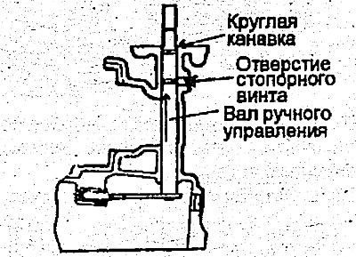
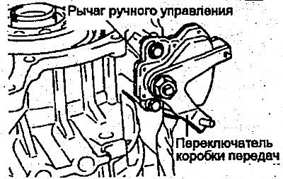
1. Insert the manual control shaft into the gearbox housing and slide it all the way towards the manual control lever.
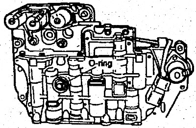
At this time, do not install the O-ring (the larger of the two O-rings) onto the manual control shaft.
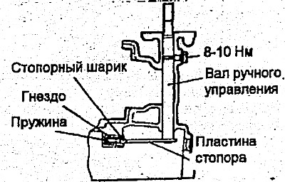
2. After installing the sealing ring on the manual control shaft, slide the shaft back into the housing, then install the lock screw and gasket. Also install the lock ball, socket and spring.
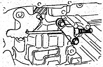
3. Install the parking spacer rod onto the stopper plate. Install the rod bracket and tighten the two bolts (20-27 Nm).
4. Before assembling the gearbox, measure the axial play of the brake (friction) of the first gear and reverse gear and select the pressure plate so that the axial play has a normal value. To do this:
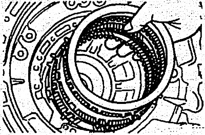
- 1) Install the clutch support plate, plate and disc into the gearbox housing.
Warning: When using new discs, be sure to soak them in automatic transmission fluid for two hours or longer.
- 2) Install the pressure plate and return spring.
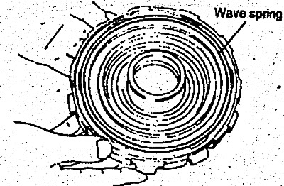
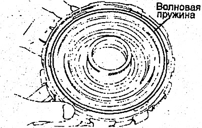
- 3) Apply grease to the wave spring and install it on the support.
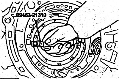
- 4) Attach the special tool (09453-21310) to the support and install the snap ring.
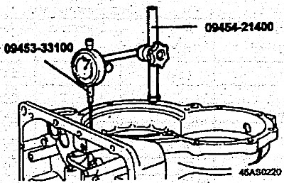
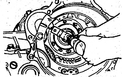
- 5) Install the watch special tool (09453-21400, 09453-33100) and a clock indicator on the rear side of the gearbox housing.
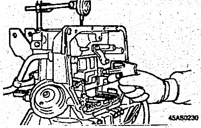
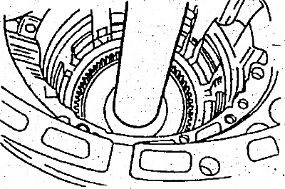
- 7) Pump air with a hand pump from the position shown in the figure. Read the indicator reading and select a pressure plate that will provide a normal gap size.
- Normal value is 0.675-1.987 mm
- Pressure plate - 5.6-6.8 mm
- 8) After selecting the pressure plate, remove the hub, brake plate, disc, reaction plate and pressure plate.
5. Install the transmission shaft and fit the outer bearing ring onto the gearbox housing with particular tightness.
6. Install the transmission shaft spring retaining ring.
7. Install the spacer sleeve onto the transmission shaft.
8. Install the rolling bearing holder into the housing.
9. Fit the driven gear onto the transmission shaft especially tightly.
10. Tighten the lock nut to the required torque (200-230 Nm).
11. Using a dial indicator, measure the axial play of the transmission shaft; then select the spacer washer(s) required to obtain its nominal value (0-0.06 mm).
12. Using a chisel, secure the lock nut to prevent it from turning.
13. Install the drive pinion assembly:
14. Install the special tool on the rear side of the gearbox housing.
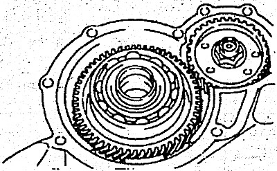
15. Using it, connect the gear wheel to the drive wheel at the transmission shaft.
16. Install the lock plate and spring retaining ring.
17. Apply special compound Three Bond 1216 to the back cover.
18. Install the back cover.
- Tightening torque: 17-22 Nm
19. Install the snap ring.
20. Install the bearing retainer. Tighten the screws to the specified torque (17-22 Nm). Apply 5 mm wide sealing material (3 M Stud Locking N 1303). The material should not extend onto the screw heads.
21. Apply a layer of petrolatum to the stubborn spot of the tire and yak #12 and install it into the planetary gear support.
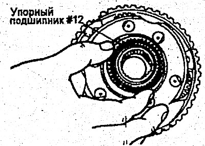
22. Install the planetary gear support into the crankcase.
23. Assemble the reverse sun wheel and forward sun wheel in the following order:
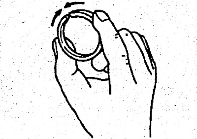
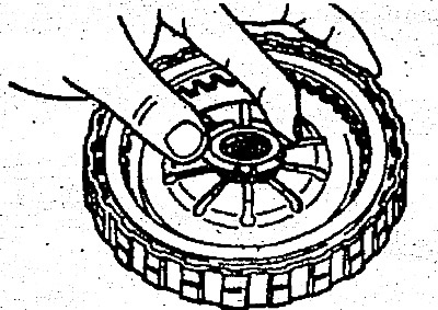
- 1) Install the O-ring and snap ring on the reverse sun gear. When installing, compress the O-ring as shown in the figure.
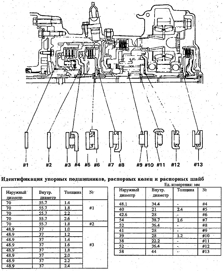
- 2) Install the thrust bearing #9 on the forward gear sun wheel.
- 3) Install the spacer ring #10 on the forward gear sun wheel.
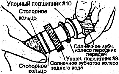
- 4) Assemble the reverse sun gear and then the forward sun gear.
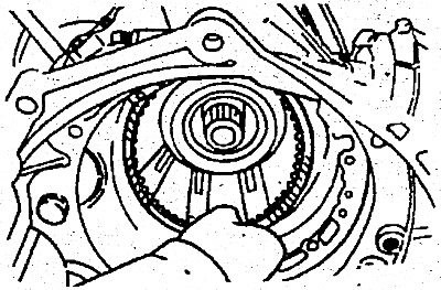
24. Install both previously assembled sun gears into the planetary gear support.
25. Install the brake disc and brake plate.
26. Install the selected brake pressure plate.
27. Install the return spring.
28. Apply a layer of petrolatum to the wave spring and install it on the center support.
29. Install two new O-rings onto the center caliper.
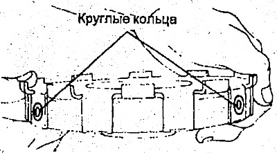
30. After applying a layer of automatic transmission fluid to the sealing rings, install the special tool (09453-21310) onto the central support and install it into the crankcase.
Warning: Make sure the wave spring is in the correct position.
31. Install the snap ring.
32. Install a new O-ring (large diameter) and D-ring (small diameter) onto the downshift servo piston and install the new O-ring into the groove around the bushing; then install the servo spring, piston and bushing into the transmission housing.
33. Press the servo and bushing into place and install the snap ring.
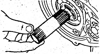
34. Install the end coupling shaft. Install it into the long keyway in the forward direction as shown in the figure.
35. Turn the thrust washer towards the return spring on the end sleeve side.
36. Install the end sleeve hub onto the end sleeve.
37. Install the thrust bearing using petrolatum #13 per end coupling hub.
38. Install the end sleeve assembly.
39. Install a new O-ring and D-ring onto the end sleeve cover.
Warnings:
- Install the D-ring so as to avoid twisting.
- Apply a sufficient amount of automatic transmission fluid to the bearing.
40. Install the end cover and secure it with four bolts.
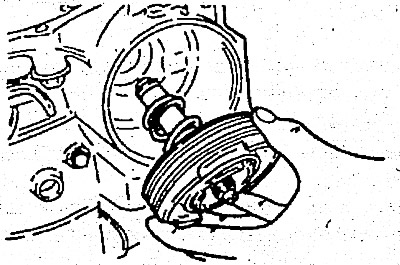
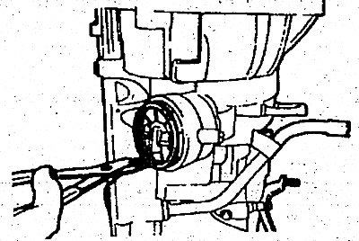
41. Install the servo drum so that its splines engage the sun wheel. Place the servo band on the drum and tighten the servo adjustment screw to hold the band.
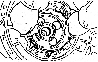
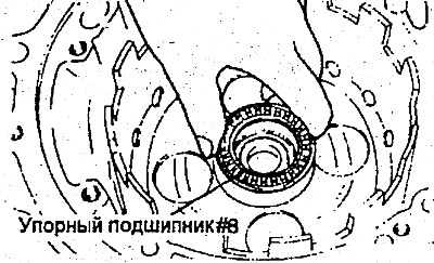
42. Apply a layer of petrolatum to the thrust bearing #8 and install it into the drum of the pushing mechanism.
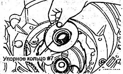
43. Apply a layer of petrolatum to the ring #7 thrust bearing and install it into the rear clutch hub.
44. Install the coupling hub onto the sun wheel sprockets.
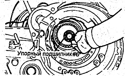
45. Using petrolatum, install the thrust bearing #6 per hub.
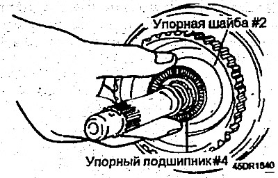
46. Apply a layer of petrolatum to the thrust ring #2 and thrust bearing #4. Install the rear coupling.
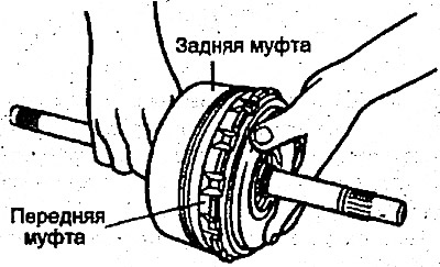
47. Connect the rear and front couplings.
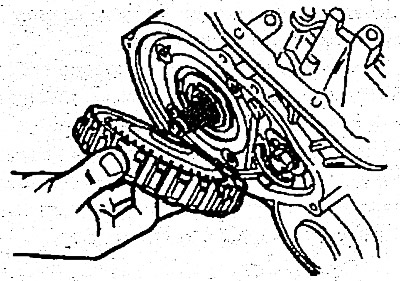
48. Install the clutch assembly.
49. If the axial clearance measured and recorded during disassembly is outside the permissible limits, adjust it by selecting a thrust ring #3.
- Nominal value - 0.3-1.0 mm
If a thrust ring of a different thickness is installed instead of a thrust ring of one thickness, the spacer washer must be replaced at the same time #1, located between the oil pump and the front clutch. Use a spacer ring that matches the thickness of the thrust ring.
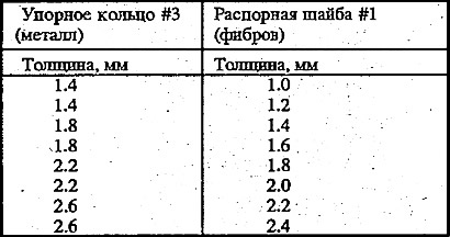
Find the correct pair: thrust ring (metal) and spacer washer (fiber) from the following table.
50. Install the used spacer washer #1 or one of those selected in accordance with paragraph 51 on the front coupling using petrolatum.
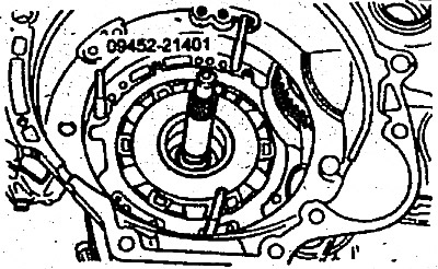
51. Install the special tool (09452-21401) on the crankcase.
52. Install the used thrust ring #3 or one of those selected in accordance with paragraph 50 on the oil pump using petrolatum.
53. Install a new gasket on the oil pump and oil pump.
54. Install a new O-ring into the groove of the oil pump housing and apply a thin film of automatic transmission fluid to the outer surface of the O-ring.
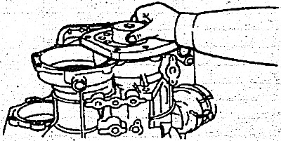
55. Install the oil pump by tightening the six bolts evenly.
When installing the oil pump, make sure the spacer washer remains in place.
56. Check the axial play of the drive shaft. Adjust if necessary (see item 50).
- Nominal value: 0.3-1.0 mm
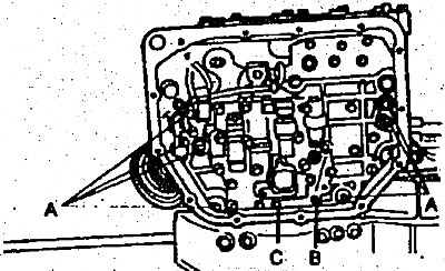
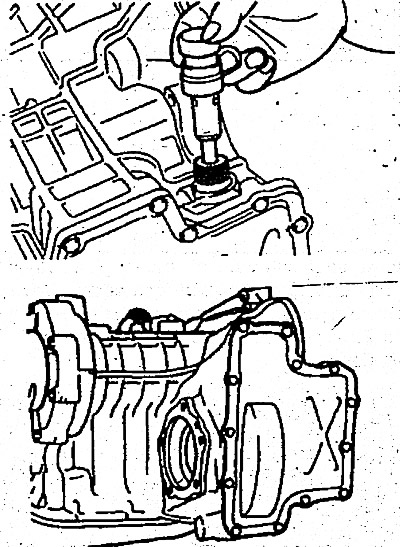
57. Install the sealing ring in the center of the top of the valve body. Install the valve body by securing the thrust plate pin (manual control shaft) in the slot of the manual control valve.
58. Replace the solenoid valve connector O-ring with a new one.
59. Tighten the valve body mounting bolts to a torque of 10-12 Nm.
- A - length 25 mm
- B - length 35 mm
- C - length 40 mm
60. Install the oil filter. Tighten the four oil filter mounting bolts to 5-7 Nm.
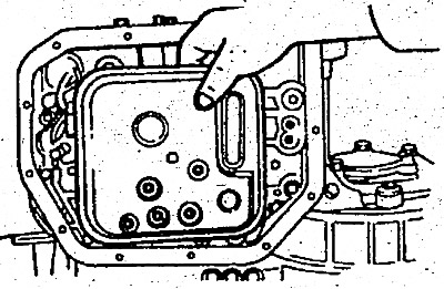
61. Install five magnets into the five recesses made in the oil pan.
62. Install a new oil pan gasket and oil pan. Tighten the 12 bolts to 10-12 Nm.
63. Install a new D-ring onto the servo switch. Press it into the crankcase and secure it with the snap ring.
64. Install the gear shifter and manual control lever.
Adjust the gear shifter.
65. Install pulse generators A and B.
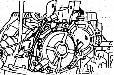
66. Install the differential assembly.
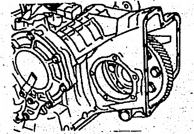
67. Place two inserts (soft solder), approximately 10 mm long and 3 mm in diameter, on the differential bearing retainer ring in the locations shown by arrows in the figure.
68. Install the differential bearing holder and tighten the bolts to the required torque (43-55 Nm).
69. Remove the differential bearing holder.
70. Remove the flattened insert from the differential bearing retainer ring.
71; Using a micrometer, measure the thickness of the flattened insert.
Select and install the spacer ring so that the differential bearing preload is within the standard value (0-0.15 mm).
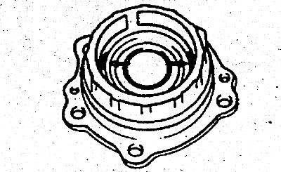
72. Apply automatic transmission fluid to the new ring and install the differential bearing retainer.
73. Install the differential bearing cover.
- Tightening torque: 60-80 Nm
74. Install the differential cover with a new Gasket.
- Tightening torque: 10-12 Nm
75. Install the speedometer drive.
76. After applying automatic transmission fluid to the outer surface of the torque converter cylinder on the oil pump side, carefully install the torque converter so as not to damage the working lip of the oil seal. Make sure that the torque converter is in engagement with the oil pump drive gear.
77. Measure the distance between the ends of the toothed ring and the torque converter housing. This distance is approximately 12 mm.