Warnings:
- Since the automatic transmission consists of precision-made parts, these parts must be handled with extreme care during disassembly and assembly to avoid damage or scratches. A rubber mat must be placed on the workbench and kept clean at all times. Do not use cloth gloves or rags during disassembly. If necessary, use nylon or paper towels.
- Metal parts can be cleaned using regular detergents, followed by thorough air drying.
- The clutch disc, plastic pressure plate and rubber parts should be cleaned using automatic transmission fluid, taking care to ensure that they are free of dust, dirt, etc.
- If the transmission unit as a whole is damaged, disassemble and clean the cooling system.
1. Remove sand, dirt, etc. from the surface of the transmission unit.
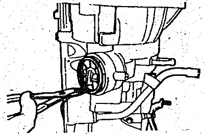
2. Place the transmission unit on a work bench with the oil pan facing down.
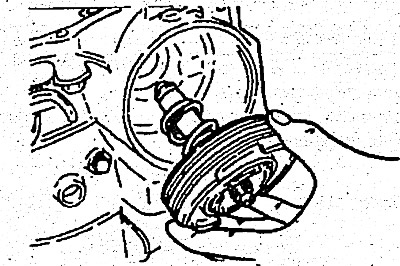
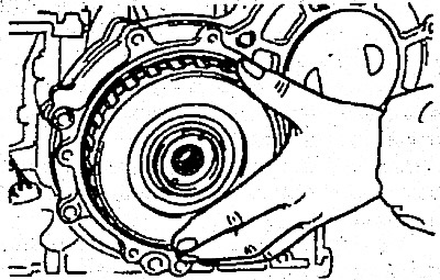
3. Remove the torque converter.
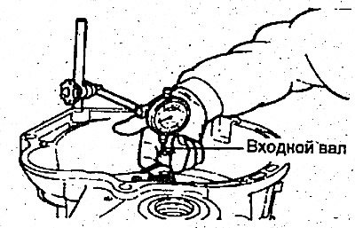
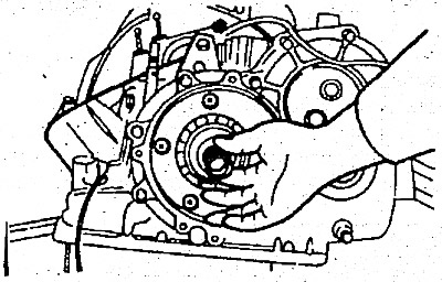
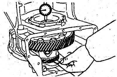
4. Measuring the input shaft end play before disassembly will usually determine whether the thrust washer needs to be replaced (except when replacing major components).
- Standard value is 0.3-1.0 mm
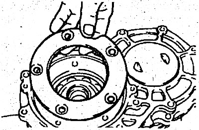
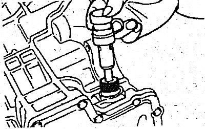
The thrust washers are located between the shaft support and the front clutch holder. Install a dial indicator on the torque converter housing.
Make sure that the indicator probe rests against the end of the input shaft.
(The original source of the article is the website: HyundaiBook.ru)
When checking the input shaft end play, move it back and forth using pliers. Be careful not to scratch the input shaft. Record the indicator reading for use when reassembling the transmission unit.
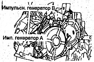
5. Summit pulse generators A and B.
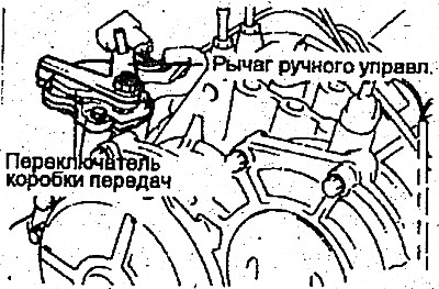
6. Remove the manual control lever, then remove the gear shifter.
7. Remove the snap ring and servo switch.
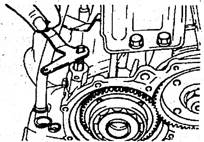
8. Remove 6 bolts using the special tool (09452-21100), and remove the oil pump assembly.
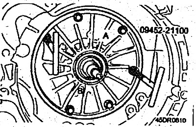
Note:
- When removing the oil pump assembly, follow the following procedure to prevent damage to the transmission.
- 1. Simultaneously and evenly turn both handles of the special tool, without tilting, to the "B" position.
- 2. When unscrewing with a special tool from the "A" side of the oil pump, if necessary, it can be easily obtained with a rubber or plastic hammer.
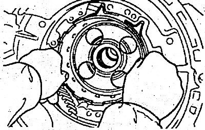
9. Remove the fiber thrust washer.
10. Remove the drive shaft and remove the front and rear couplings.
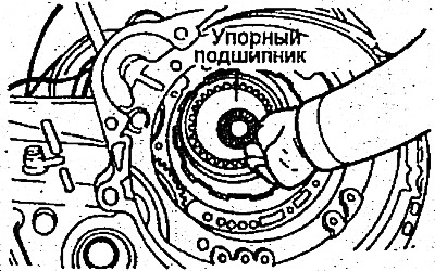
11. Remove the thrust bearing.
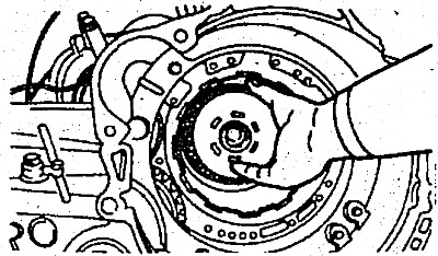
12. Remove the clutch hub.
13. Remove the thrust bearing ring and bearing.
14. Remove the downshift servo drum.
15. Remove the tape from this servo mechanism.
16. Remove the spring retaining ring.
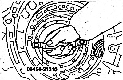
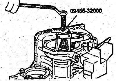
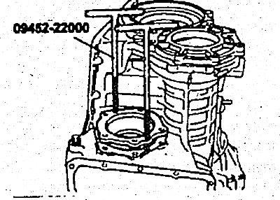
17. Attach special tool 909453-21310 to the center support. Holding the handle, pull the center support straight up.
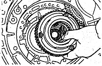
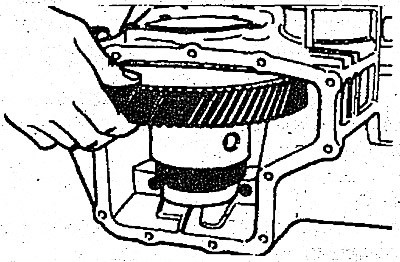
18. Remove the forward and reverse gear wheels.
19. Remove the planetary gear support and thrust bearing.
20. Remove the wave spring, return spring, backing plate, brake disc and brake plate.
21. Remove the bolts securing the end sleeve cover, the cover mount and the end sleeve cover.
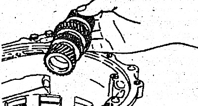
22. Remove the end sleeve.
23. Remove the thrust plate.
24. Remove the end sleeve hub and thrust bearing.
25. Remove the end coupling shaft.
26. Remove the oil pan and gasket.
27. Remove the oil filter from the valve body.
28. Loosen the oil temperature sensor mounting bolt; after removing it from the bracket side, pull it out from the connector side.
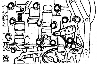
29. Compress the tabs of the solenoid valve wiring sleeve and insert it.
30. Unscrew the 10 valve mechanism housing bolts. Remove the housing.
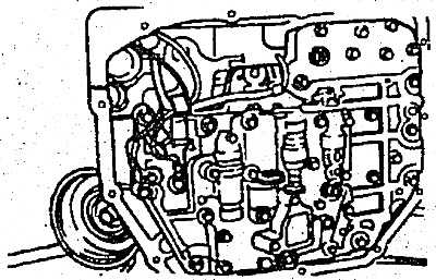
31. Using an impact driver, loosen the bolts (or a chisel or similar tool).
32. Remove the bearing holder.
33. Remove the spring retaining ring.
34. Loosen the bolts securing the back cover and remove the back cover.
35. Remove the cotter pin from the transmission shaft lock nut.
36. Set the manual control lever to position "P".
37. Remove the lock nut.
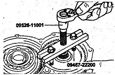
38. Using the special tool, remove the driven gear of the transmission shaft.
39. Remove the outer race of the tapered roller bearing.
40. Remove the spring retaining ring.
41. Remove the transmission shaft and tapered roller bearing.
42. Move the manual control lever from position "P" to position "N".
43. Remove the spring retaining ring from the outer flange.
44. Remove the locking plate.
45. Using a special tool or press, remove the outer flange and drive gear.
46. Remove the speedometer bushing.
47. Remove the differential cover and gasket.
48. Before removing the differential gear, measure the differential gear axial play using a dial indicator.
- Standard value - 0-0.15 mm
49. Remove the 5 bolts securing the differential bearing retainer.
50. Using the special tool, remove the differential bearing holder.
51. Loosen the mounting bolts and remove the bearing cover.
52. Remove the differential.
53. Loosen the two bolts and remove the parking spacer rod.
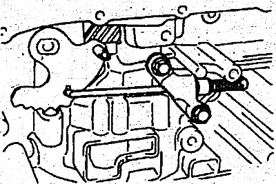
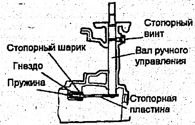
54. Loosen the lock screw and remove the manual control shaft assembly. At the same time, remove the steel ball, its seat and spring.
55. Remove the downshift servo spring retaining ring.
56. Remove the downshift servo piston assembly.