


Contents: Removal ⇓ Installation ⇓
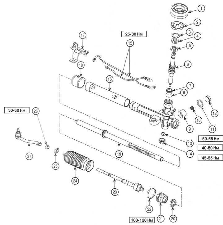
1. Protective cuff; 2. Dust cover; 3. Retaining ring; 4. Seal; 5. Bearing; 6. Gear; 7. Seal; 8. Needle bearing; 9. Rack stop; 10. Spring; 11. Lock nut; 12. Plug; 13. Gear nut; 14. Plug; 15. Amplifier pipes; 16. Steering gear housing; 17. Bracket; 18. Rubber bushing; 19. Toothed rack; 20. Seal; 21. Rack travel limiter; 22. Dust cover clamp; 23. Steering rod; 24. Anther; 26. Lock nut; 25. Dust cover clamp; 27. Tie rod end
Removal
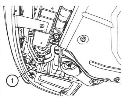
1. Disconnect the return hose (1) and drain the working fluid.
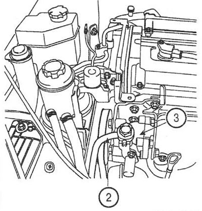
2. Disconnect the pressure pipe (2) from the power steering pump (3) by unscrewing the hollow screw. Tightening torque: 55-65 Nm.
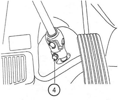
3. Loosen the intermediate shaft joint bolt (4). Tightening torque: 13-18 Nm.
4. Remove the front wheels.
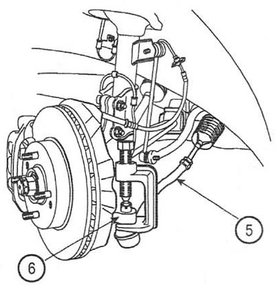
5. Using a suitable puller, disconnect the tie rod end (5) from the steering knuckle (6). Tightening torque: 24-34 Nm.
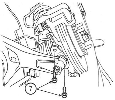
6. Loosen the screws (7) of the ball joint. Tightening torque: 100-120 Nm.
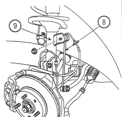
7. Disconnect the stabilizer struts (8) from the shock absorber strut (9) on both sides. Tightening torque: 35-45 Nm.
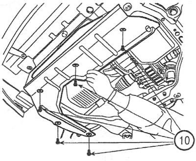
8. Unscrew the screws (10) and remove the front engine mudguard.
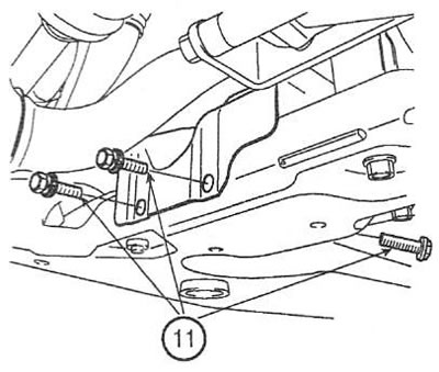
9. Unscrew the screws (11) and remove the heat shield.
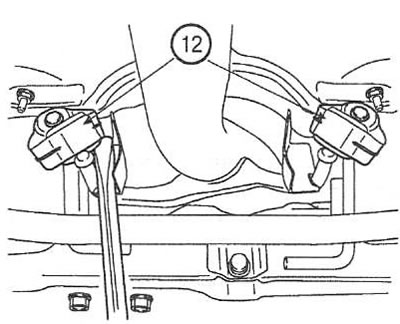
10. Remove the muffler hanger (12).
11. Unscrew the bolts (13 and 14) of the power unit supports. Tightening torque: 50-65 Nm.
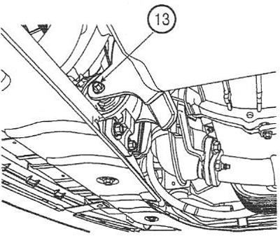 |
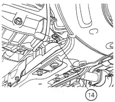 |
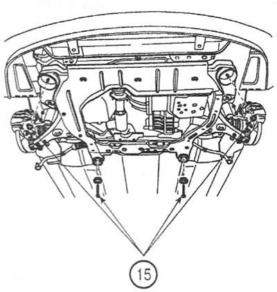
12. Unscrew the screws and nuts (15) and remove the subframe. Tightening torque: 95-120 Nm.
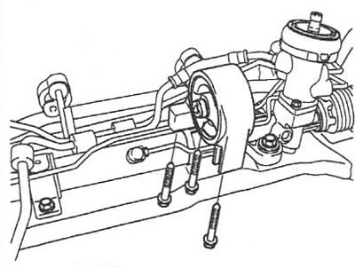
13. Loosen the screws and remove the rear support of the power unit. Tightening torque: 50-60 Nm.
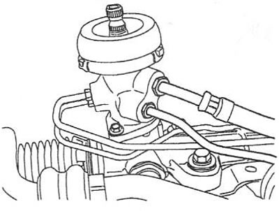
14. Disconnect the booster tubes from the spool valve housing.
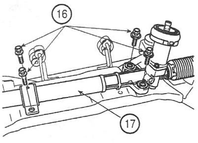
15. Loosen the screws (16) and remove the steering gear (17). Tightening torque: 50-60 Nm.
Installation
16. Installation is carried out in the reverse order of removal.