
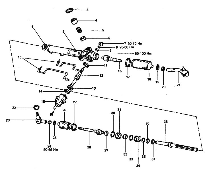
Steering gear.
1 - oil seal, 2 - steering gear housing, 3 - lock nut, 4 - guide rack cover, 5 - guide rack spring, 6 - rack guide with insert, 7 - plug, 8 - self-locking nut, 9 - bearing, 10 - power steering tubes, 11 - oil seal, 12 - worm with control valve, 13 - bearing, 14 - oil seal, 15 - control valve housing, 16 - left steering rod, 17 - inner boot clamp, 18 - steering rod boot, 19 - outer boot clamp, 20 - steering rod lock nut, 21 - left steering rod end, 22 - joint protective boot, 23 - right steering rod end, 24 - steering rod lock nut traction, 25 - inner boot clamp, 26 - steering rod boot, 27 - outer boot clamp, 28 - right steering rod, 29 - lock washer, 30 - lock ring, 31 - rack travel limiter, 32 - oil seal, 33 - sealing ring, 34 - rack bushing, 35 - oil seal, 36 - sealing ring, 37 - oil seal, 38 - steering rack.
Removal
1. Drain the power steering fluid (see chapter "Maintenance and general check and adjustment procedures").
2. Loosen the intermediate shaft mounting bolt.
- Tightening torque: 15-20 Nm
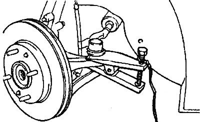
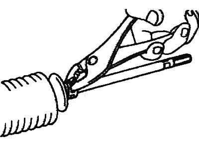
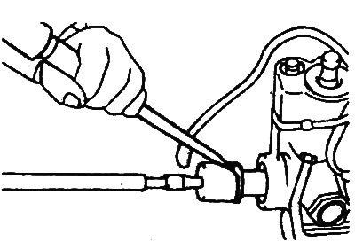
3. Using the special tool, disconnect the tie rod end from the steering knuckle.
4. Remove the exhaust system components (see chapter "Exhaust system").
5. Unscrew the bolts of the front and rear power unit supports.
- Tightening torque: 60-80 Nm
6. Unscrew the subframe bolts.

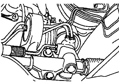
7. Remove the power steering pipes.
- Tightening torque: 12-18 Nm
8. Loosen the steering gear mounting bolts and remove the steering gear assembly with rubber gaskets.
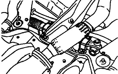
Note: To remove the steering gear, first move the rack to the right and then to the left.
Caution: When removing the steering gear assembly, remove the steering gear slowly and very carefully to avoid damaging the steering rod boots.
9. If necessary, remove the anti-roll bar.
Disassembly
1. Loosen the tie rod lock nuts, then remove the tie rod ends and nuts.
2. Remove the ball joint protective cover.
3. Remove the inner clamps of the steering rod boots.
4. Remove the outer clamps of the steering rod boots.
5. Slide the steering rod boots towards the ends.
6. Disconnect the power steering pipes from the steering gear.
7. Slowly move the rack to drain the power steering fluid from the steering gear housing.
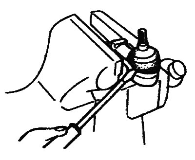
8. Using a chisel and hammer, bend back the bent portions of the lock washers.
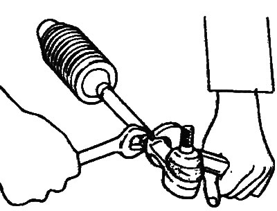
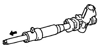
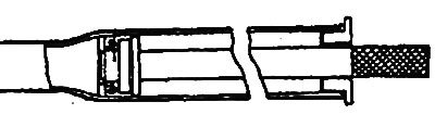
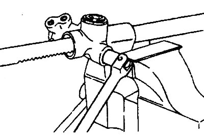
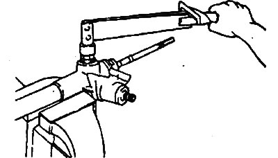
9. Using the special tool, unscrew the steering rods as shown in the figure and remove the lock washers.
- Tightening torque: 80-100 Nm
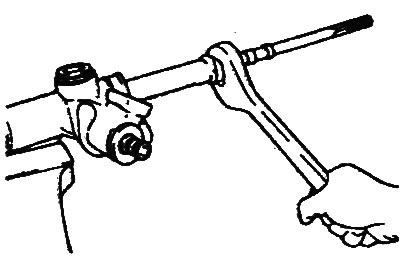
Caution: Be careful not to damage the rack.
10. Unscrew the guide rail cover lock nut.
- Tightening torque: 50-70 Nm
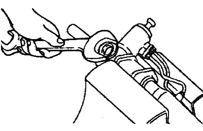
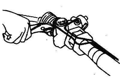
11. Using the special tool, unscrew the guide rail cover.
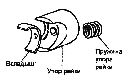
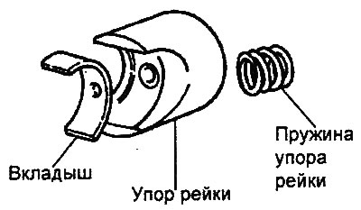
12. Remove the rack guide spring, rack guide and bushing from the steering gear housing.
13. Unscrew the plug and self-locking nut.
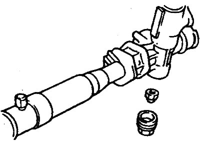
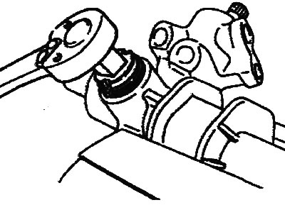
14. Unscrew the two bolts and remove the control valve housing.
15. Using a hammer with a plastic striker, remove the worm with the control valve, remove the seals and bearing.
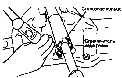
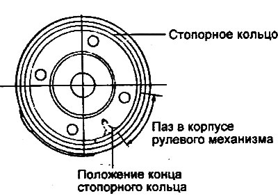
16. Turn the rack travel stop clockwise until the end of the locking ring comes out of the groove in the steering gear housing.
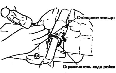
17. Once the end of the locking ring has come out of the groove in the steering gear housing, turn the rack travel stop counterclockwise and remove the locking ring.
Caution: Be careful not to damage the steering rack during disassembly.
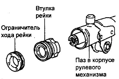
18. Remove the rack travel limiter, oil seal and rack bushing assembly with the sealing ring and oil seal from the steering rack, and remove the rack and oil seal from the steering gear housing.
19. Remove the sealing ring and oil seal from the steering rack.
20. Remove the sealing ring from the rack bushing.
21. Remove the seal from the rack bushing.
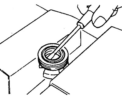
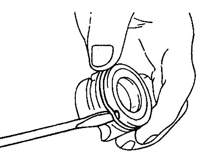
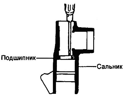
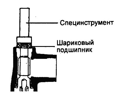
22. Using a punch, remove the bearing from the housing.
23. Remove the bearing and seal from the housing.
24. Using special tools, remove the lock washer and seal.
Examination
1. Check the steering rack.
- a) Check that the rack teeth are not worn or damaged.
- b) Check the seal seating surface for damage.
- c) Make sure that there is no bending or twisting of the steering rack.
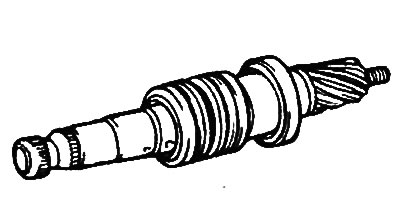
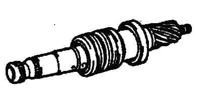
2. Check the worm with the control valve.
- a) Check that the worm teeth are not worn or damaged.
- b) Check the seal seating surface for damage.
3. Check the bearings.
- a) Make sure that the bearings rotate smoothly and that there is no extraneous noise when operating.
- b) Check that there is no excessive play in the bearings.
- c) Ensure the structural integrity of the bearings.
4. Check for damage on the inner surface of the steering gear housing.
5. Check the steering rod boots for wear, cracks and tears.
6. Check the O-rings and seals for excessive wear or damage.
Assembly
1. Apply power steering fluid to the lip of the steering rack oil seal.
- Working fluid: PSF-3
2. Using the special tools, install the oil seal and snap ring into the steering gear housing as shown in the figure.
3. Apply grease to the bearing.
- Lubrication: SAE J310a, NGLI No.2
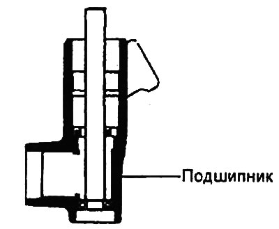
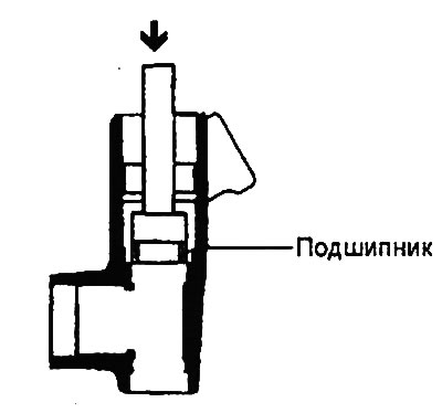
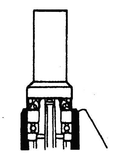
4. Using the special tool, install the bearing as shown in the figure.
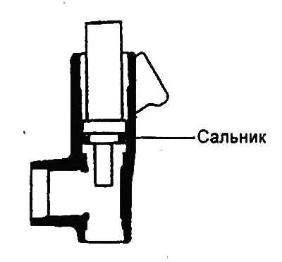
5. Using the special tool, install the oil seal as shown in the figure.
Note:
- Do not confuse the direction of installation of the oil seal.
- Use only a new seal.
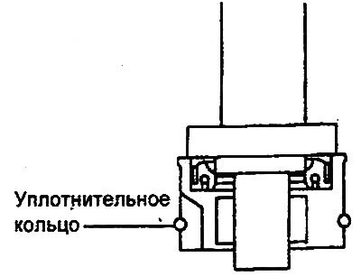
6. Install the oil seal into the rack bushing.
7. Apply power steering fluid to the O-ring and install it onto the bushing as shown in the figure.
- Working fluid: PSF-3
8. Apply grease to the steering rack teeth.
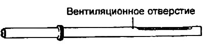
Caution: Do not fill the ventilation hole in the steering rack with grease.
- Grease: SAE J310a, NLGI No.2 EP
9. Install the seal and O-ring on the rack.
10. Install the seal, rack, rack bushing assembly with sealing ring and seal, and rack travel limiter into the steering gear housing.
11. Align the hole in the rack travel limiter with the groove in the steering gear housing, install the locking ring into the hole in the limiter. Turn the rack travel limiter and finally fix the locking ring.
Caution: After installing the retaining ring, its ends must not be visible through the groove in the steering gear housing.
12. Apply working fluid and grease to the worm with the control valve, then install the assembly with the seal into the valve body.
- Working fluid: PSF-3
- Grease: SAE J310a, NLGI No.2 EP
13. Using the special tool, install the bearing.
14. Install the oil seal using a special tool.
15. Turn the worm clockwise until it stops and tighten the self-locking nut.
- Tightening torque: 20-30 Nm
Note: Do not reuse the self-locking nut.
16. Apply anaerobic (semi-drying) sealant to the threaded portion of the plug and tighten it.
- Tightening torque: 50-70 Nm

17. Lock the plug in two places using a punch.
18. Install the new lock washer and tie rod. Chisel the edges of the lock washer in two places on the tie rod.
Note:
- Align the tabs on the lock washer with the recesses in the steering rod.
- Do not reuse the lock washer.
19. Install the insert, rack guide and rack guide spring into the steering gear housing in the sequence shown in the figure.
20. Install the guide rail cover.
- a) Apply sealant to the threaded portion of the guide cover,
- b) Set the rack to the central position and, using the special tool, tighten the cover of the guide rack. Turn the cover approximately 10° and tighten the cover lock nut.
Tightening torque:
- guide rail covers: 20-25 Nm
- cover locknuts: 50-70 Nm
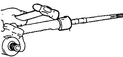
21. Check the worm rotation moment.
- a) Measure the worm rotation torque as shown in the figure.
- Scrolling moment: 0.6-1.3 Nm
- b) If the torque is not within specification, check and replace the guide rack cover if necessary.
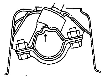
22. Install the steering rod covers.
- a) Apply grease to the surfaces shown in the figure.
- Grease: SAEJ310a, NLGI No.2 EP
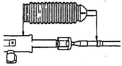
- b) Install the cover and tighten the clamps.
Note:
- Use only new clamps.
- Do not allow the clamps to become twisted.
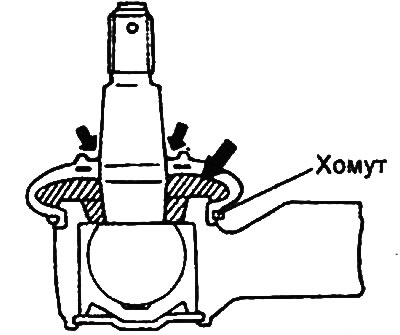
23. Fill the inner cavity with grease and apply grease to the edge of the protective boot of the tie rod end joint. Fix the protective boot on the ball joint with a clamp, placing it in the groove of the tie rod end.
- Grease: SAE J310a, NLGI No.2 EP
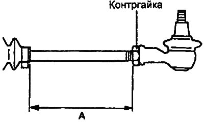
24. Tighten the left and right steering rod ends so that the length of the protruding parts of the left and right rods is the same and corresponds to the nominal value. Secure the ends with lock nuts.
- Nominal value "A": 47.2 mm
Installation
1. The steering gear is installed in the reverse order of removal; the tightening torques for the bolts and nuts are specified in the description of the removal procedure and in the assembly drawing "Steering gear".
2. When installing the rubber pads, align the protrusion of the pad and the recess in the subframe.
3. After installation:
- Make sure there are no leaks of working fluid.
- Make sure the steering wheel rotates smoothly.
- Check and, if necessary, adjust the front wheel alignment angles (see chapter "Suspension").