
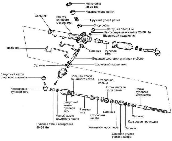
Fig. 5.22. Steering mechanism
Drain the working fluid from the power steering system.
Disconnect the pressure and return pipes from the steering gear fittings.
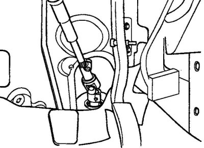
Fig. 5.23. Disconnecting the propeller shaft
Disconnect the steering cardan shaft from the steering gear inside the passenger compartment (Fig. 5.23).
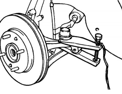
Fig. 5.24. Disconnecting the steering rod end
Using a special tool (09568-31000), disconnect the steering rod end from the steering knuckle (Fig. 5.24).
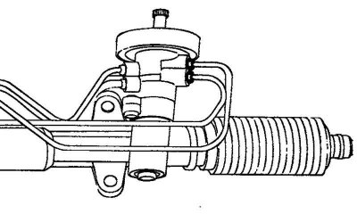
Fig. 5.25. Steering gear tubes
Remove the steering gear tubes (Fig. 5.25).
Remove the steering gear mounting bolts and remove the steering gear assembly together with the rubber mounts.
Caution! When removing the steering gear assembly, remove the steering gear slowly and very carefully so as not to damage the protective boots of the steering rods and the protective boots of the ball joints of the steering rod ends.
Disassembly
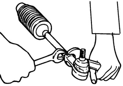
Fig. 5.26. Removing the tie rod end
Remove the tie rod end from the tie rod (Fig. 5.26).
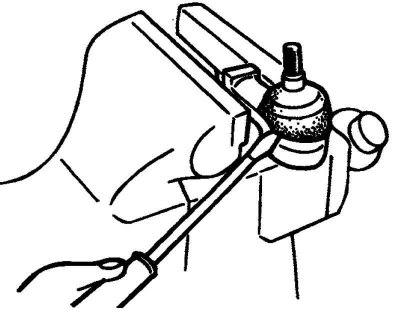
Fig. 5.27. Removing the dust cover from the ball joint
Remove the boot from the ball joint (Fig. 5.27).
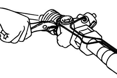
Fig. 5.28. Removing the large clamp securing the steering rod protective boot
Remove the large clamp securing the steering rod protective boot (Fig. 5.28).
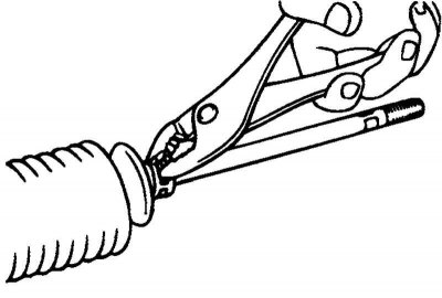
Fig. 5.29. Removing the small clamp securing the steering rod protective boot
Remove the small clamp of the steering rod protective boot (Fig. 5.29).
Pull the protective cover from the steering gear housing onto the steering rod.
Note: When replacing the protective cover, make sure there is no rust on the steering rack.
Disconnect the steering gear tubes from the valve body and steering gear and remove them.
Slowly move the rack to drain the working fluid from the steering gear housing.
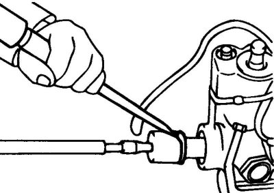
Fig. 5.30. Chiselling the lock washer securing the steering rod and steering rack
Using a chisel, chisel out the lock washer that secures the steering rod and steering rack (Fig. 5.30).
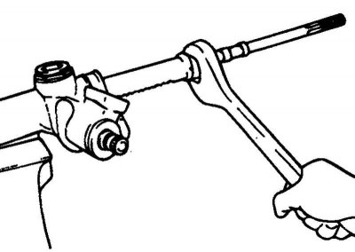
Fig. 5.31. Removing the steering rod
Remove the steering rod from the steering rack (Fig. 5.31).
Caution! Be careful when removing the steering rod from the steering rack, do not bend the rack.
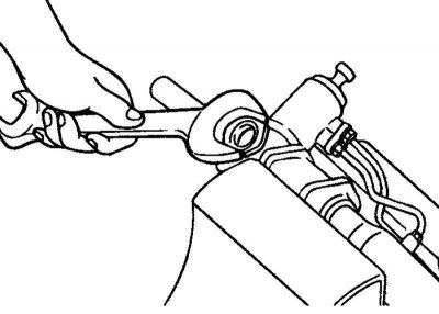
Fig. 5.32. Unscrewing the rack stop cover lock nut
Unscrew the rack stop cover lock nut (Fig. 5.32).
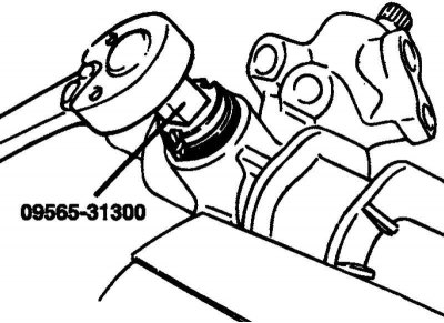
Fig. 5.33. Removing the rack stop cover
Using a special tool (09565-31300), remove the rack stop cover (Fig. 5.33).
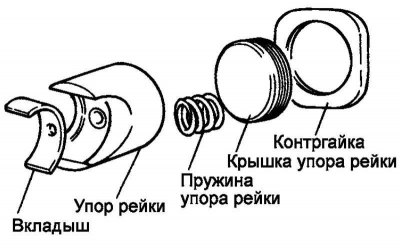
Fig. 5.34. Steering gear housing components
Remove the rack stop spring, rack stop, rack stop cover and insert from the steering gear housing (Fig. 5.34).
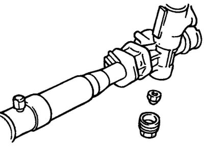
Fig. 5.35. Plug and self-locking nut
Remove the plug and self-locking nut (Fig. 5.35).
Remove the snap ring using a snap ring plier.
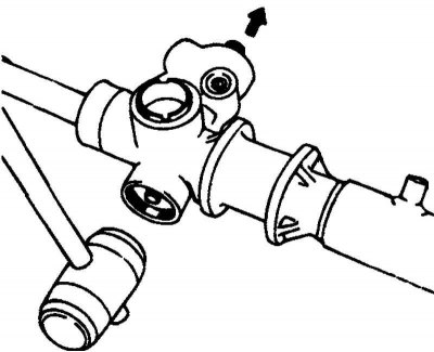
Fig. 5.36. Removing the drive gear and valve assembly
Remove the drive gear and valve assembly together with the upper seal using a plastic-faced hammer (Fig. 5.36).
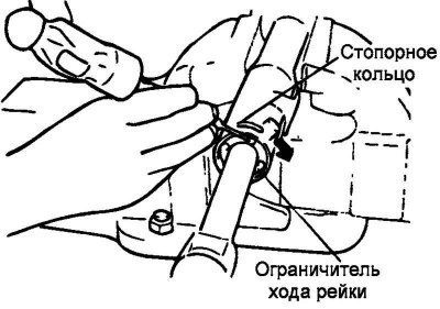
Fig. 5.37. Turning the locking ring before removal
Turn the rack travel limiter clockwise until the end of the locking ring comes out of the groove in the steering gear housing (Fig. 5.37).
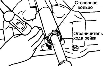
Fig. 5.38. Removing the retaining ring from the groove of the steering gear housing
Once the end of the locking ring has come out of the groove in the steering gear housing, turn the rack travel stop counterclockwise and remove the locking ring (Fig. 5.38).
Caution! Do not damage the rack during disassembly.
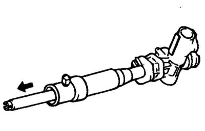
Fig. 5.39. Removing the rack travel limiter
Remove the rack travel limiter, rack support bushing and steering rack from the steering gear housing on the plunger side (Fig. 5.39).
Attention! After removing the rack, replace the seal on the housing side with a new one.
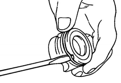
Fig. 5.40. Removing the O-ring
Remove the O-ring from the rack support bushing (Fig. 5.40).
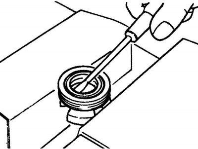
Fig. 5.41. Removing the seal from the rack support bushing
Remove the seal from the rack support sleeve (Fig. 5.41).
Checking the steering rack
Check the steering rack teeth for wear or damage.
Check the seal contact surface for excessive wear or damage.
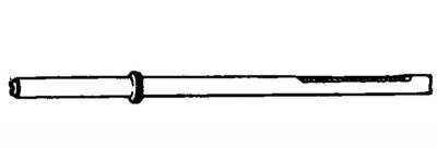
Fig. 5.42. Steering rack
Check the straightness of the steering rack (no bending or twisting) (Fig. 5.42).
Check the O-ring for excessive wear or damage.
Check the seal for excessive wear or damage.
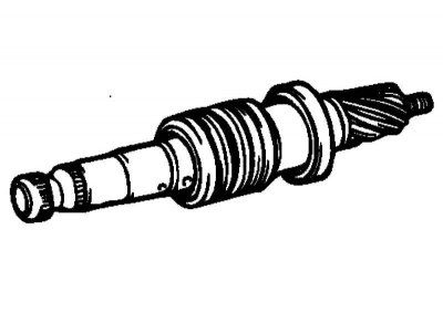
Fig. 5.43. Leading gear
Check the pinion teeth for wear or damage (Fig. 5.43).
Check the seal contact surface for excessive wear or damage.
Check the O-ring for excessive wear or damage.
Check the seal for excessive wear or damage.
Check the smooth rotation and absence of extraneous noise when the bearings are operating.
Check for excessive play in the bearings.
Check that the needles do not fall out of the needle bearing.
Check the inner surface of the steering gear housing cylinder for damage.
Check the protective covers for wear, cracks or tears.
Assembly
Apply the recommended working fluid to the working lip of the steering rack oil seal along its entire circumference.
Recommended working fluid: PSF-3.
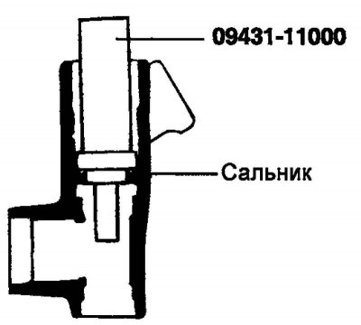
Fig. 5.44. Installing the seal in the steering gear housing
Using a special tool (09431-11000), install the oil seal into the steering gear housing as shown in Figure 5.44.
Attention! Mark the installation direction of the seal.
Caution: Use only a new seal.
Apply the recommended working fluid to the steering rack support bushing seal around its entire circumference.
Recommended working fluid: PSF-3
Install the seal on the rack support bushing.
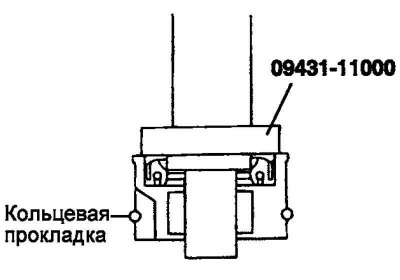
Fig. 5.45. O-ring installation diagram
Apply the recommended working fluid to the O-ring and install it on the support bushing of the steering rack using a special tool (09431-11000) (Fig. 5.45).
Apply recommended grease to the steering rack teeth.
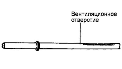
Fig. 5.46. Steering rack ventilation hole
Caution! Do not fill the steering rack ventilation hole with grease (Fig. 5.46).
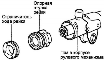
Fig. 5.47. Installing the rack support sleeve and rack travel limiter
Insert the rack into the steering gear housing, then install the rack support sleeve and rack travel limiter (Fig. 5.47).
Insert the locking ring into the hole of the rack stopper through the hole in the steering gear housing when the holes are aligned. Turn the rack stopper and finally fix the locking ring.
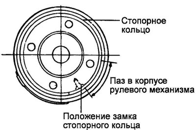
Fig. 5.48. Position of the retaining ring lock
Caution! After installing the retaining ring, its ends should not be visible through the hole in the steering gear housing (Fig. 5.48).
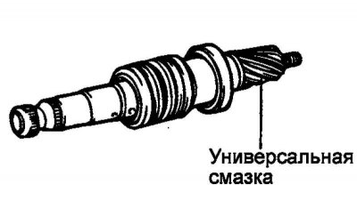
Fig. 5.49. Place of application of consistent lubricant
Apply the recommended operating fluid and recommended grease to the pinion and valve assembly and install into the steering gear housing (Fig. 5.49).
Recommended working fluid: PSF-3.
Recommended grease: SAE J310a, NLGI No.2 general purpose.
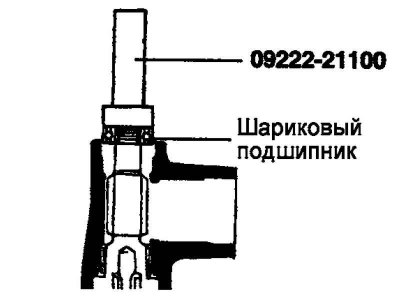
Fig. 5.50. Ball bearing installation diagram
Install the ball bearing using a special tool (09222-21100) (Fig. 5.50).
Install the drive gear and valve assembly into the valve body.
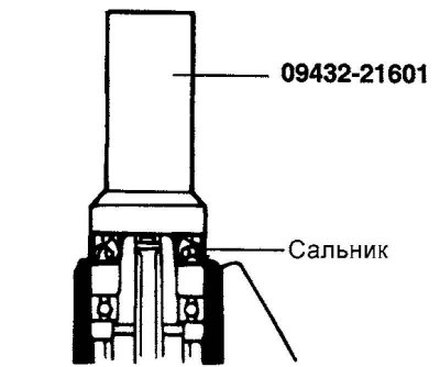
Fig. 5.51. Seal installation diagram
Install the seal using a special tool (09432-21601) (Fig. 5.51).
Install the snap ring using a snap ring plier.
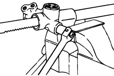
Fig. 5.52. Tightening the self-locking nut
Turn the drive gear clockwise until it stops and tighten the self-locking nut (Fig. 5.52).
Caution: Always replace the self-locking nut with a new one.
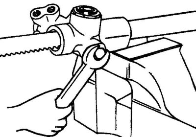
Fig. 5.53. Tightening the plug
Apply a rubber-forming sealant (semydrying sealant) onto the threaded part of the plug and tighten to the nominal torque (Fig. 5.53).
Tightening torque of the plug: 50–70 Nm.
Use a punch to counter-tighten the plug in two places.
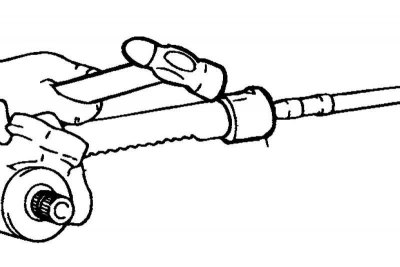
Fig. 5.54. Caulking the ends of the lock washer
Install a new lock washer and tie rod. Chisel the edges of the lock washer in two places on the tie rod (Fig. 5.54).
Note: Insert the tabs of the lock washer into the recesses of the steering rod in two places.
Note: Always replace the lock washer with a new one before installation.
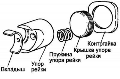
Fig. 5.55. Sequence of installation of components in the steering gear housing
Install the insert, rack stop, rack stop spring and rack stop cover into the steering gear housing in the sequence shown in Figure 5.55.
Apply a rubber-forming sealant (semydrying sealant) on the threaded part of the rack stop cover before installing it.
Set the rack to the center position, then insert the rack stop cover into the steering gear housing. Using a special tool, tighten the rack stop cover to a torque of 20-25 Nm. Unscrew the rack stop cover by about 20 degrees and tighten the rack stop cover lock nut to the rated torque.
Tightening torque of the lock nut: 50–70 Nm.
After adjustment, install the rack stop cover together with the lock nut.
Attention! If it is not possible to adjust the drive gear rotation torque within the specified rotation angle value, check or replace the rack stop parts and rack stop cover.
Install and tighten the steering tube fasteners to the specified torque, then install the rubber mounts in place using special glue (adhesive).
Apply the recommended grease to the location where the small clamp of the protective boot is installed on the steering rod (in the groove on the rod).
Recommended grease: SAE J310a, NLGI No.2 general purpose.
Install a new large tie rod end boot clamp.
Note: Always replace the large boot clamp with a new one before installing the tie rod end boot.
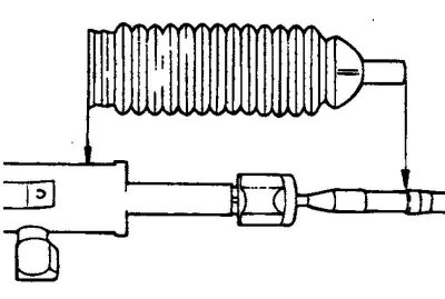
Fig. 5.56. Scheme of correct installation of protective cover
Install the steering rod protective cover in place, preventing it from twisting (Fig. 5.56).
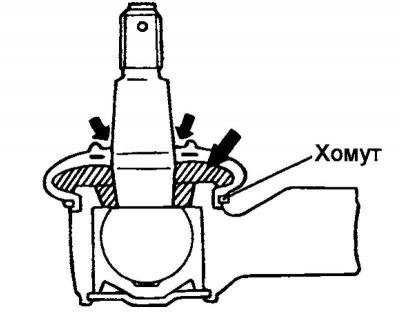
Fig. 5.57. Large clamp installation diagram
Fill the inner cavity of the protective boot of the ball joint of the tie rod end (A) and the working edge of the ball joint (B) with the recommended grease. Apply the recommended sealant to the sealing edge of the protective boot and fix it to the ball joint using a clamp (Fig. 5.57).
Recommended grease: SAE J310a, NLGI No.2 general purpose.
Tighten the left and right tie rod ends so that the protruding length of the rod on the left and right is the same and corresponds to the nominal value. Secure the position with a lock nut.
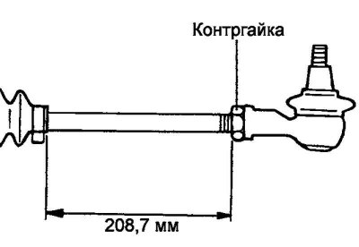
Fig. 5.58. Length of the protruding part of the steering rod
Length of the protruding part of the steering rod: nominal value – 208.7 mm (Fig. 5.58).
Install the steering gear assembly onto the vehicle.