
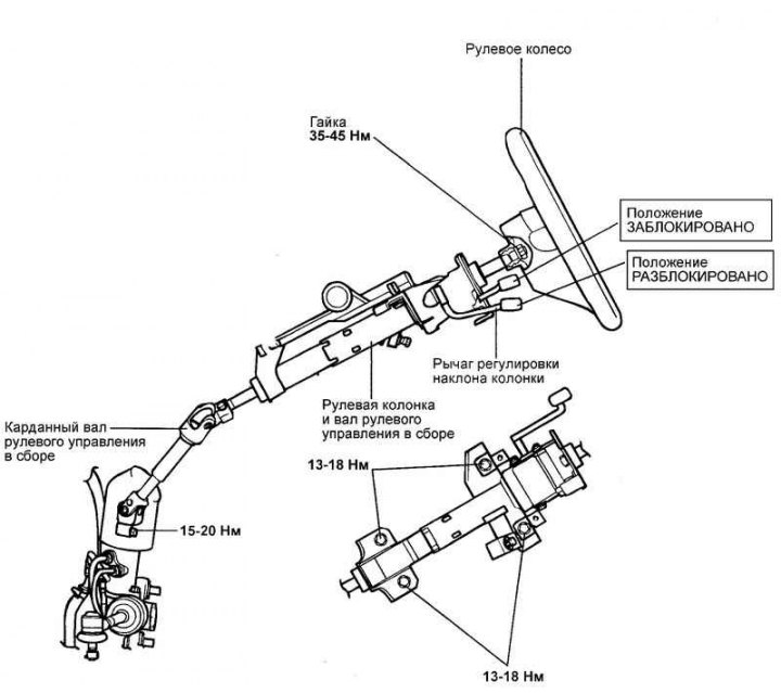
Fig. 5.12. Steering shaft assembly
Removal
Disconnect the cable from the negative battery terminal.
Remove the horn cover by prying it from both sides under the steering wheel.
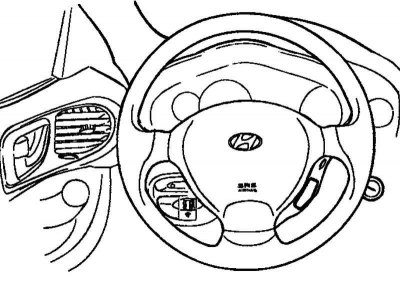
Fig. 5.13. Airbag module
Remove the two bolts using a hex wrench (Fig. 5.13).
Disconnect the driver's front airbag (DAB) and horn connector, and remove the steering wheel lock nut.
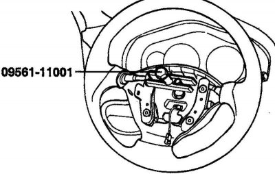
Fig. 5.14. Removing the steering wheel
Remove the steering wheel using the special tool (SST) (Fig. 5.14).
Caution: Do not use a hammer to remove the steering wheel, as this may damage the telescopic shaft.
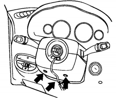
Fig. 5.15. Steering column lower casing mounting bolts
Remove the upper and lower steering column casings (Fig. 5.15).
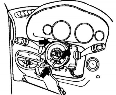
Fig. 5.16. Removing the combination switch
Disconnect the connectors from the steering column combination switch and remove it (Fig. 5.16).
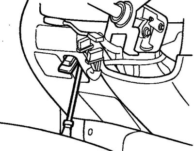
Fig. 5.17. Removing the switch
Remove the switch from the left side of the lower instrument panel cover (Fig. 5.17).
Remove the lower instrument panel cover.
After disconnecting all connectors, remove the steering column and steering shaft assembly.
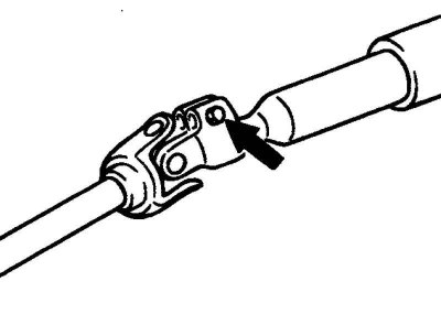
Fig. 5.18. Connecting bolt of the cardan shaft and the drive gear
Remove the connecting bolt of the cardan shaft and the drive gear (Fig. 5.18).
Remove the steering driveshaft assembly from the steering gear.
Remove the boot mounting bolts.
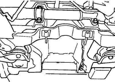
Fig. 5.19. Steering column mounting bolts
Remove the 4 steering column mounting bolts (Fig. 5.19).
Drain the working fluid and disconnect the return and discharge hoses.
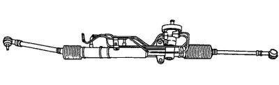
Fig. 5.20. Steering shaft assembly
Remove the steering column and steering shaft together with the steering cardan shaft and boot (Fig. 5.20).
Examination
Check the steering shaft for deformation or damage.
Check the upper and lower bearings for wear or damage.
Check the driveshaft connection for excessive play, deformation or roughness of moving parts.
Check the steering column mounting bracket for cracks and deformations.
Check the lid or protective cap for deformation.
Check that the steering column lock is working properly.
The article is borrowed from the website: hyundaibook
Assembly
Assembly is carried out in the reverse order of disassembly.
When installing the steering column lock, position its bracket and the steering shaft so that the groove in the steering shaft is aligned with the hole in the steering column.
Installation
Before installation, apply general purpose grease to the inside surface of the bearing groove and the contact surfaces of the boot and cover assembly.
Connect the lower steering shaft to the steering cardan shaft.
Note: Install the propeller shaft to the steering gear first, then install the steering column and steering shaft assembly.
Install the boot onto the steering shaft assembly.
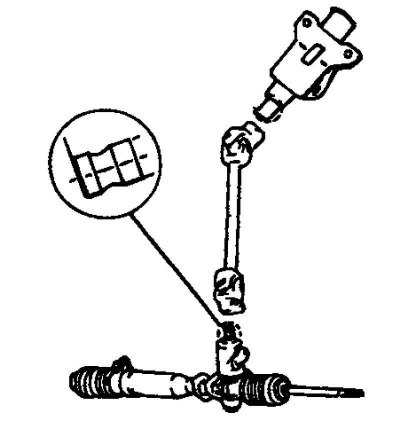
Fig. 5.21. Connecting the steering column to the mounting bracket
Install the steering column assembly by connecting it to the steering column assembly mounting bracket (Fig. 5.21).
Install the steering column combination switch and connect the connectors.
Install the lower instrument panel cover, upper and lower steering column covers.
Install the steering wheel.
Note: Do not use a hammer during installation, as this may damage the steering column telescopic shaft.