
Removal
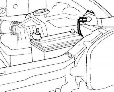
Fig. 5.13. Disconnecting the wire from the negative terminal of the battery
Disconnect the wire from the negative terminal of the battery (Fig. 5.13).
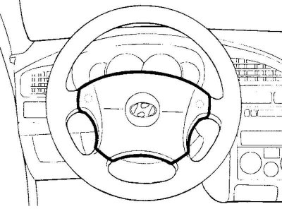
Fig. 5.14. Airbag module
Remove the driver's airbag module (Fig. 5.14).
Note: On models without a driver airbag, remove the horn switch cover.
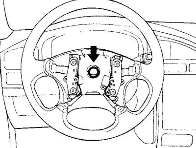
Fig. 5.15. Steering wheel mounting nut
Loosen the self-locking nut securing the steering wheel (Fig. 5.15).
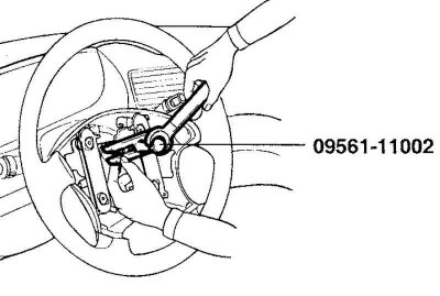
Fig. 5.16. Removing the steering wheel
Apply alignment marks to the relative positions of the steering shaft and steering wheel, then remove the steering wheel using a special tool (Fig. 5.16).
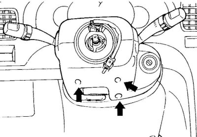
Fig. 5.17. Upper and lower steering column cover mounting bolts
Remove the upper and lower steering column casings (Fig. 5.17).
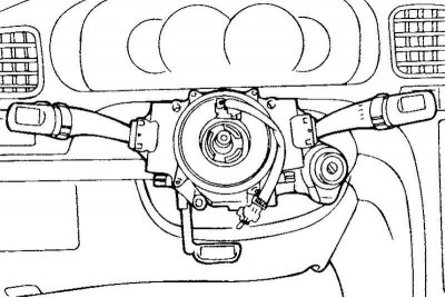
Fig. 5.18. Steering column combination switch connectors
Disconnect the connectors from the steering column combination switch (Fig. 5.18).
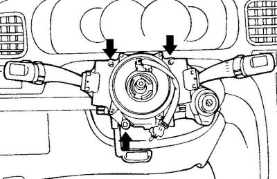
Fig. 5.19. Bolts for mounting the steering column combination switch
Remove the three mounting bolts shown in Figure 5.19, then remove the steering column combination switch assembly.
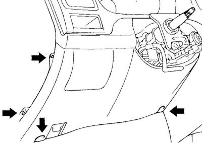
Fig. 5.20. Screws for fastening the lower cover of the instrument panel
Remove the four mounting screws shown in Figure 5.20 and remove the lower instrument panel cover.
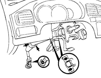
Fig. 5.21. Steering column assembly and steering cardan shaft mounting bolts
Remove the five bolts securing the steering column assembly and the steering propeller shaft, shown in Figure 5.21.
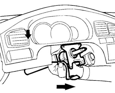
Fig. 5.22. Removing the steering column and steering shaft
Loosen the mounting bolts and nuts, then remove the steering column and steering shaft assembly (Fig. 5.22).
Examination
Check the steering shaft for deformation or damage.
Check the connection points for excessive play, damage and jamming (smooth movement).
Check the steering cardan joint bearings for wear or damage.
Installation
Installation is carried out in the reverse order of removal.