
Contents: Checking and adjusting before…⇓ Checking the total torque of the…⇓ Checking the resistance to rotation…⇓ Checking the protective cover ⇓ Disassembly ⇓ Checking the steering rack ⇓ Assembly ⇓ Installation ⇓
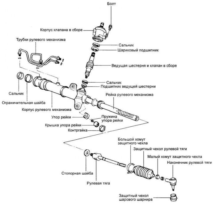
Fig. 5.35. Steering gear components
Checking and adjusting before disassembling
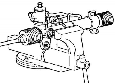
Fig. 5.36. Securing the steering gear in a vice
Place soft metal pads (brass or aluminum plates) on the vice jaws to prevent damage to the steering gear and secure the latter in the vice (Fig. 5.36).
Caution! When installing the steering gear in a vice, secure it so that the jaws of the vice are aligned with the location of the mounting bracket. Any other method of securing in a vice may damage the steering gear.
Checking the total torque of the steering gear pinion
(preload of the steering gear pinion shaft)
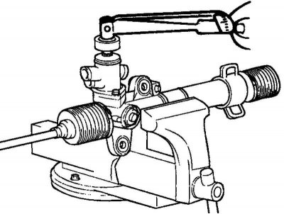
Fig. 5.37. Rotation of the rack and pinion steering gear
To check the total torque of the steering gear pinion, use a special key to rotate the steering gear pinion within one revolution for 4–6 s (Fig. 5.37).
Total torque of the steering gear pinion (nominal value): 0.6–1.3 N·m.
Note: Measure the pinion torque at full steering rack travel.
If the measured value does not match the standard value, first adjust the position of the steering rack stop cover and then check the total torque of the steering gear pinion again.
If the total torque of the pinion gear cannot be adjusted, check the thrust cap, thrust spring and steering rack thrust and replace parts if necessary.
Checking the resistance to rotation of the steering rod joint
Make 10 strong turns of the tie rod end.
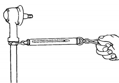
Fig. 5.38. Measuring the rotational resistance of the steering rod joint
Using a spring dynamometer, measure the resistance to rotation of the steering rod joint (Fig. 5.38).
Tie rod joint torque (nominal value): 8–22 N (2–5 N·m).
If the measured value exceeds the standard value, replace the steering rod assembly.
Attention! If the measured value is less than the nominal value, but the steering rod turns smoothly, without excessive play, then such a tip is suitable for operation. If the measured value is less than 4.3 N (1 N·m), replace the steering rod assembly.
Checking the protective cover
Check the protective cover for damage or deterioration.
Check that the protective cover is attached correctly.
If any defects are found in the protective cover, replace it with a new one.
Disassembly
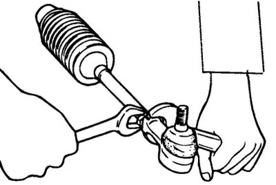
Fig. 5.39. Removing the steering rod end
[The text is provided by the web resource: HYUNDAIBOOK.RU]
Remove the tip from the steering rod (Fig. 5.39).
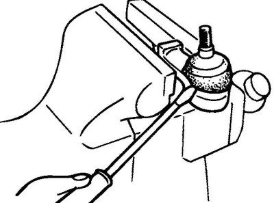
Fig. 5.40. Removing the ball joint protective cover
Clamp the tie rod end in a vice, then remove the ball joint protective boot (Fig. 5.40).
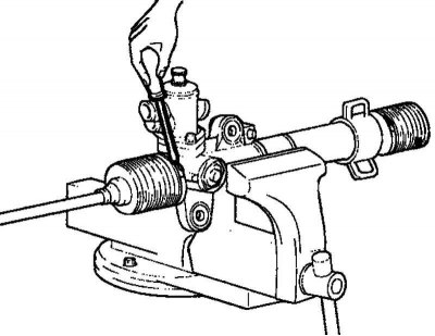
Fig. 5.41. Removing the large clamp securing the steering rod protective boot
Remove the large clamp securing the steering rod protective boot (Fig. 5.41).
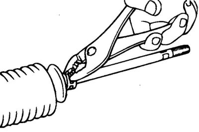
Fig. 5.42. Removing the small clamp securing the steering rod protective boot
Remove the small clamp securing the steering rod protective boot (Fig. 5.42).
Pull the protective cover from the steering gear housing onto the steering rod.
Note: When replacing the protective cover, make sure there is no rust on the steering rack.
Disconnect the steering gear tubes from the valve body and steering gear and remove them.
Slowly move the rack to drain the working fluid from the steering gear housing.
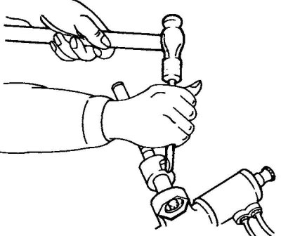
Fig. 5.43. Chiselling the lock washer
Using a chisel, chisel out the lock washer that secures the steering rod and steering rack (Fig. 5.43).
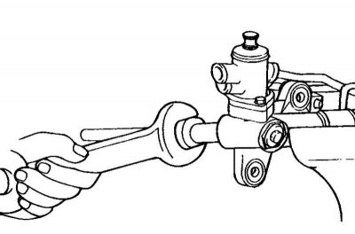
Fig. 5.44. Removing the steering rod from the steering rack
Remove the steering rod from the steering rack (Fig. 5.44).
Caution! Be careful when removing the steering rod from the steering rack, do not bend the rack.
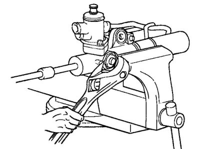
Fig. 5.45. Removing the rack stop cover lock nut
Unscrew the rack stop cover lock nut (Fig. 5.45).
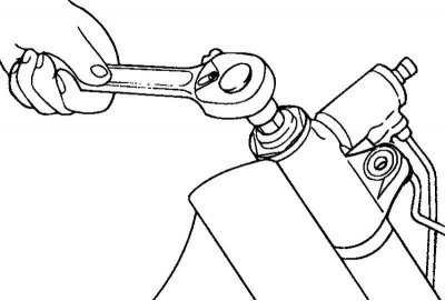
Fig. 5.46. Removing the rack stop covers
Remove the rack stop covers using a 14 mm tool socket (Fig. 5.46).

Fig. 5.47. Rack components
Remove the rack stop spring, rack stop, rack stop cover and insert from the steering gear housing (Fig. 5.47).
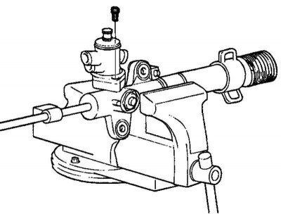
Fig. 5.48. Valve body mounting bolts
Unscrew the two mounting bolts and remove the valve body assembly (Fig. 5.48).
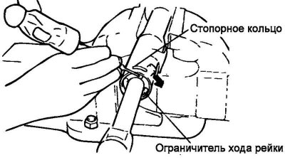
Fig. 5.49. Turning the rack travel limiter clockwise
Turn the rack travel limiter clockwise until the end of the locking ring comes out of the groove in the steering gear housing (Fig. 5.49).
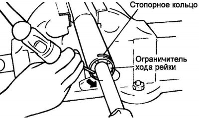
Fig. 5.50. Removing the retaining ring
Once the end of the locking ring has come out of the groove in the steering gear housing, turn the rack travel stop counterclockwise and remove the locking ring (Fig. 5.50).
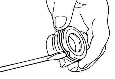
Fig. 5.51. Removing the O-ring
Remove the ring gasket from the rack support bushing (Fig. 5.51).
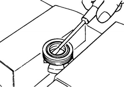
Fig. 5.52. Removing the oil seal
Remove the seal from the rack support sleeve (Fig. 5.52).
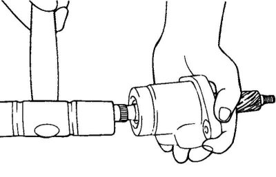
Fig. 5.53. Removing the drive gear and valve assembly from the valve body
Using light taps from a plastic-faced hammer, carefully remove the drive gear and valve assembly from the valve body (Fig. 5.53).
Using a special tool, remove the seal and ball bearing from the valve body.
Caution: Be careful not to damage the inner surface of the pinion cylinder in the steering gear housing.
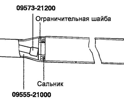
Fig. 5.54. Removing the seal from the steering gear housing
Using a special tool, remove the seal from the steering gear housing (Fig. 5.54).
Caution: Be careful not to damage the inner surface of the rack cylinder in the steering gear housing.
Checking the steering rack
Check the steering rack teeth for wear or damage.
Check the seal contact surface for excessive wear or damage.
Fig. 5.55. Steering rack
Check the straightness of the steering rack (no bending or twisting) (Fig. 5.55).
Check the O-ring for excessive wear or damage.
Check the seal for excessive wear or damage.
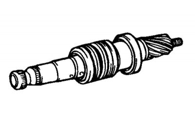
Fig. 5.56. Drive gear
Check the pinion teeth for wear or damage (Fig. 5.56).
Check the seal contact surface for excessive wear or damage.
Check the O-ring for excessive wear or damage.
Check the seal for excessive wear or damage.
Check the smooth rotation and absence of extraneous noise when the bearings are operating.
Check for excessive play in the bearings.
Check that the needles do not fall out of the needle bearing.
Check the inner surface of the steering gear housing cylinder for damage.
Check the protective covers for wear, cracks or tears.
Assembly
Apply the recommended PSF-3 power steering fluid to the steering rack seal lip around its entire circumference.
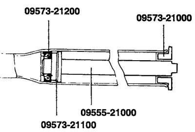
Fig. 5.57. Installation diagram of the limiting washer and seal
Install the limit washer and seal into the steering gear housing as shown in Figure 5.57.
Apply the recommended working fluid to the steering rack support bushing seal around its entire circumference.
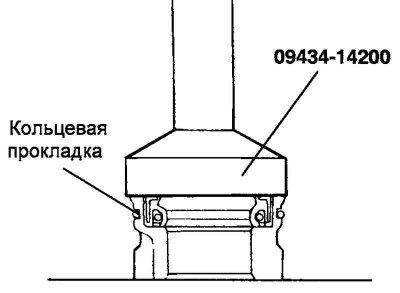
Fig. 5.58. Diagram of installation of the seal on the support sleeve of the rack
Install the seal on the rack support sleeve (Fig. 5.58).
Apply the recommended working fluid to the O-ring and install it onto the steering rack support bushing.
Apply recommended grease to the steering rack teeth.
Recommended grease: SAE J310, NLGI #2 general purpose.
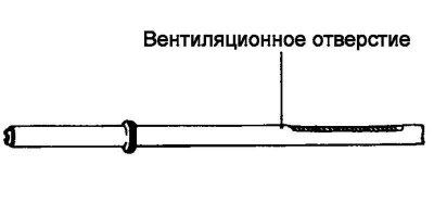
Fig. 5.59. Ventilation hole
Note: Do not fill the steering rack vent hole with grease (Fig. 5.59).
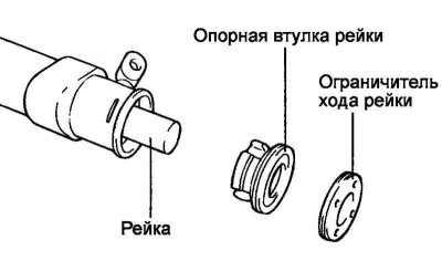
Fig. 5.60. Installing the rack components
Insert the rack into the steering gear housing, then install the rack support sleeve and rack travel limiter (Fig. 5.60).
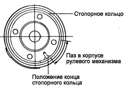
Fig. 5.61. Retaining ring installation diagram
Insert the locking ring into the rack stop hole through the hole in the steering gear housing when the holes are aligned. Turn the rack stop and finally fix the locking ring (Fig. 5.61).
Caution! After installing the retaining ring, its ends should not be visible through the hole in the steering gear housing.
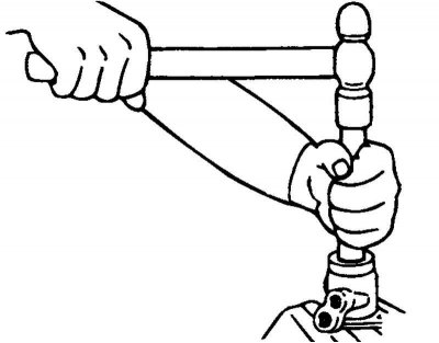
Fig. 5.62. Installing the seal and ball bearing into the valve body
Using a special tool, install the seal and ball bearing into the valve body (Fig. 5.62).
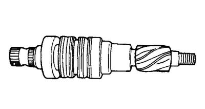
Fig. 5.63. Drive gear
Apply the recommended working fluid to the pinion and valve assembly, then install them into the valve body (Fig. 5.63).
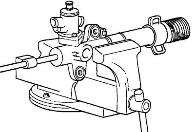
Fig. 5.64. Installing the valve body and ring gasket on the steering gear body
Apply the recommended working fluid to the seal and install it into the steering gear housing. Install the valve body assembly and the O-ring onto the steering gear housing (Fig. 5.64).
Install a new lock washer and tie rod. Chisel the edges of the lock washer in two places on the tie rod.
Note: Insert the tabs of the lock washer into the recesses of the steering rod in two places.
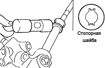
Fig. 5.65. Lock washer installation diagram
Always replace the lock washer with a new one before installation (Fig. 5.65).
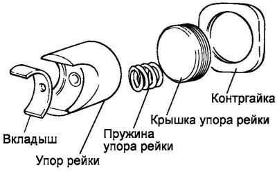
Fig. 5.66. Assembly of the rack
Install the insert, stop, spring and rack stop cover into the steering gear housing in the sequence shown in Figure 5.66.
Apply a rubber-forming sealant (semydrying sealant) on the threaded part of the rack stop cover before installing it.
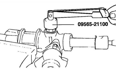
Fig. 5.67. Installing the rack stop cover
Set the rack to the central position, then insert the rack stop cover into the steering gear housing. Using the special tool, tighten the rack stop cover to a torque of 15 N·m (Fig. 5.67).
Turn the rack stop cover 30–60° and tighten the rack stop cover lock nut to a nominal torque of 50–70 N·m.
Install and tighten the steering tube fasteners to the specified torque, then install the rubber mounts in place using special glue (adhesive).
Apply the recommended silicone grease to the location where the small clamp of the protective boot is installed on the steering rod (in the groove on the rod).
Install a new large tie rod end boot clamp.
Note: Always replace the large boot clamp with a new one before installing the tie rod end boot.
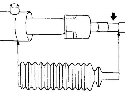
Fig. 5.68. Installing the steering rod protective cover
Install the steering rod protective cover in place, preventing it from twisting (Fig. 5.68).
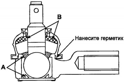
Fig. 5.69. Lubrication application areas
Fill the inner cavity of the protective boot of the ball joint of the tie rod end (A) and the working edge of the ball joint (B) with the recommended grease (Fig. 5.69).
Apply the recommended sealant to the sealing edge of the protective boot and secure it to the ball joint using a clamp.
Recommended lubricant:
- A - POLY LUB GLY 801K or equivalent;
- B - SHOWA SUNLIGHT MB2 or equivalent.
Recommended sealant for the protective boot sealing edge: THREE BOND.
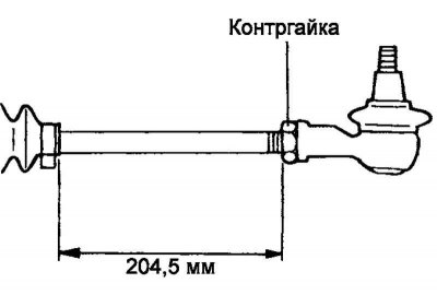
Fig. 5.70. Tie rod end lock nut
Tighten the left and right steering rod ends so that the length of the protruding part of the rod on the left and right is the same and corresponds to the nominal value. Secure the position with a lock nut (Fig. 5.70).
Length of protruding part of steering rod: 204.5 mm.
Check the total torque of the steering gear pinion (preload of the steering gear pinion shaft).
Installation
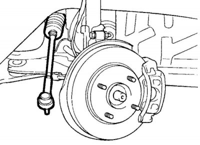
Fig. 5.71. Installing the steering gear
Install the steering gear assembly through the right wheel arch (Fig. 5.71).
Install the steering shaft boot support plate.
Attach the steering shaft boot to its support plate using a new band clamp.
Connect the steering shaft and steering column assembly to the steering gear assembly.
Install the remaining parts in the reverse order of removal.
Bleed the power steering hydraulic system.