
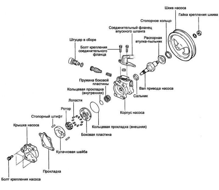
Fig. 5.76. Power steering pump
Removal
Disconnect the pressure hose from the power steering pump.
Disconnect the inlet hose from the connecting flange on the power steering pump and drain the working fluid into a suitable container.
Loosen the power steering pump mounting bolts before removing the pump drive belt.
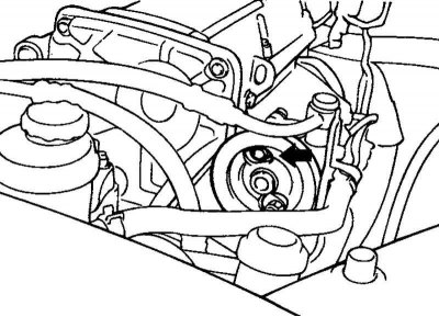
Fig. 5.77. Pump drive belt tension adjustment bolt
Loosen the pump drive belt tension adjustment bolt (Fig. 5.77).
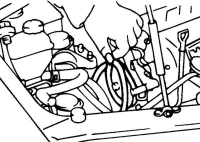
Fig. 5.78. Removing the pump drive belt
Remove the pump drive belt from the power steering pump pulley (Fig. 5.78).
Completely unscrew the power steering pump mounting bolts and the pump drive belt tension adjustment bolt.
Remove the power steering pump assembly.
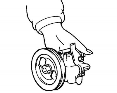
Fig. 5.79. Removing the pump
Note: Be careful when removing the pump, do not spill the liquid inside it (Fig. 5.79).
Remove the power steering pump mounting bracket.
Disassembly
Remove the inlet hose connecting flange and O-ring from the power steering pump.
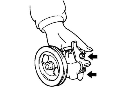
Fig. 5.80. Power steering pump cover mounting bolts
Loosen the four mounting bolts and remove the power steering pump cover (Fig. 5.80).
Remove the cam washer.
Remove the rotor and blades.
Remove the side plate.
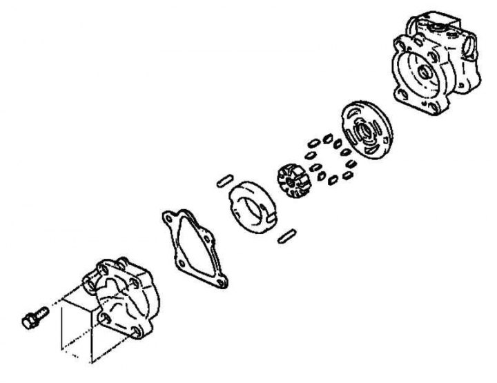
Fig. 5.81. Pump components
Remove the inner and outer O-rings (Fig. 5.81).
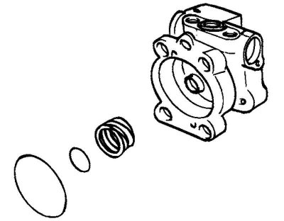
Fig. 5.82. Side plate spring
Remove the side plate spring (Fig. 5.82).
Note: When reassembling the pump, install a new pump cover gasket and new O-rings.
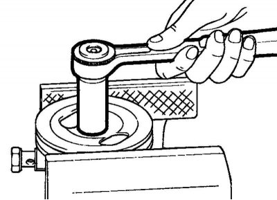
Fig. 5.83. Unscrewing the pump pulley mounting nut
Clamp the pump drive pulley in a vice, unscrew the mounting nut and remove the spring washer (Fig. 5.83).
Remove the pulley from the pump drive shaft.
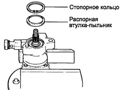
Fig. 5.84. Retaining ring and spacer sleeve-dust cover
Remove the retaining ring using a retaining ring plier, then remove the spacer sleeve-dust cover (Fig. 5.84).
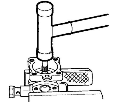
Fig. 5.85. Removing the pump drive shaft
Using light blows from a plastic hammer on the rotor side, knock out the pump drive shaft (Fig. 5.85).
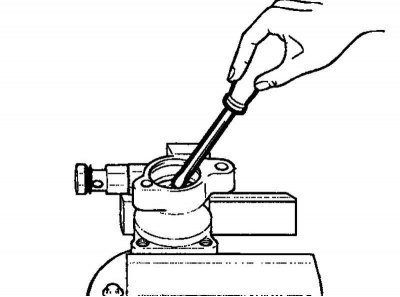
Fig. 5.86. Removing the seal from the power steering pump housing
Using a screwdriver, remove the seal from the power steering pump housing (Fig. 5.86).
Note: Always install a new seal when reassembling the pump.
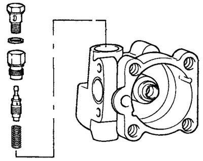
Fig. 5.87. Power steering pump housing nipple
Remove the nipple from the power steering pump housing, then remove the fluid flow control valve and valve spring (Fig. 5.87).
Remove the O-ring from the fitting.
Caution: Do not disassemble the fluid flow control valve.
Examination
Check the length of the flow control valve spring in a free state (without load).
Valve spring length in free state: 36.5 mm.
Check the fluid flow control valve for deformation (bending).
Check the pump drive shaft for wear or damage.
Check the pump drive belt for wear or deterioration.
Check for "stepped" wear on the rotor blades and slots.
Check for "stepped" wear on the contact surface of the blades and cam washer.
Check the blades for damage.
Check for wear tracks on the side plate or contact areas between the drive shaft and the pump cover.
Assembly
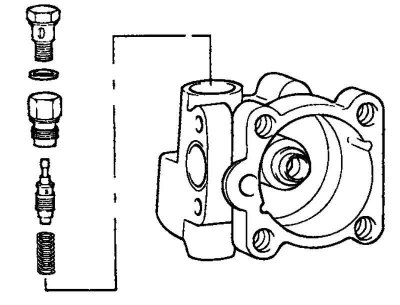
Fig. 5.88. Components of the power steering pump nipple
Install the valve spring, fluid flow control valve and fitting into the power steering pump housing (Fig. 5.88).
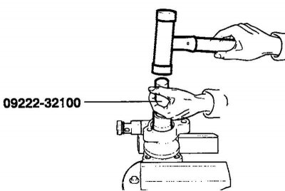
Fig. 5.89. Installing a new seal
Using a special tool, install a new seal into the power steering pump housing (Fig. 5.89).
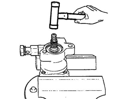
Fig. 5.90. Installing the pump drive shaft
Insert the pump drive shaft assembly into the power steering pump housing, then install the spacer sleeve-dust cover and retaining ring (Fig. 5.90).
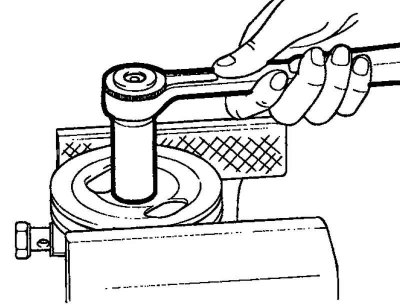
Fig. 5.91. Installing the power steering pump pulley
Install the power steering pump pulley (Fig. 5.91).
Install the spring and inner O-ring.
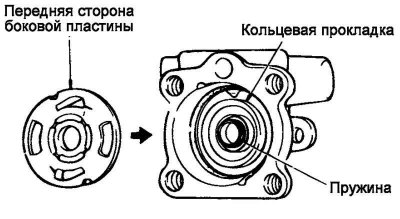
Fig. 5.92. Installing the lower ring gasket
Insert the outer O-ring into the side plate, then install the side plate into the power steering pump housing (Fig. 5.92).
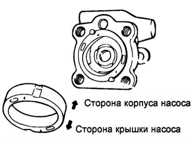
Fig. 5.93. Installing the cam washer
Install the locking pins into the holes in the pump body, then install the cam washer, paying particular attention to the correct installation direction (Fig. 5.93).
Install the rotor.
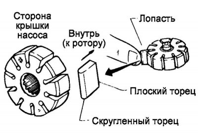
Fig. 5.94. Installing the pump rotor blade
Install the blades so that their rounded ends are on the outside (from the cam washer side) (Fig. 5.94).
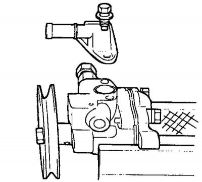
Fig. 5.95. Power steering pump cover
Install the gasket and pump cover assembly (Fig. 5.95).
Install the O-ring and the inlet hose connecting flange.
Installation
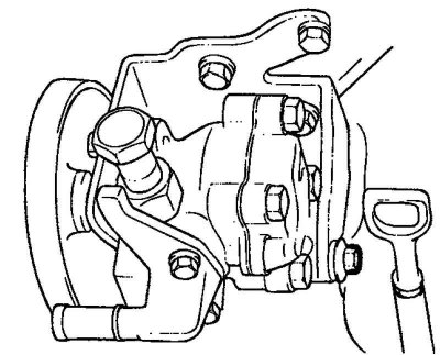
Fig. 5.96. Installing the power steering pump
After installing the bracket and pump, place the drive belt on the pump pulley and adjust its tension. Tighten the tension adjustment bolt to the specified torque (Fig. 5.96).
Tightening torque: 35–50 Nm.
Connect the inlet hose.
Tighten the pressure hose fastening to the power steering pump.
Note: When installing the pressure hose, make sure it is not kinked or has any possibility of contact with other parts of the vehicle.
Fill the power steering system with the recommended PSF-3 power steering fluid.
Bleed the power steering hydraulic system.
Check the power steering pump pressure.