Vehicles without power steering
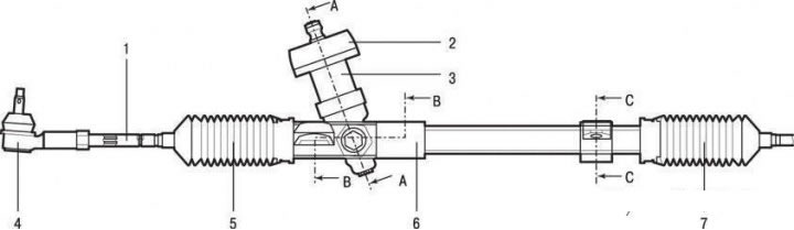
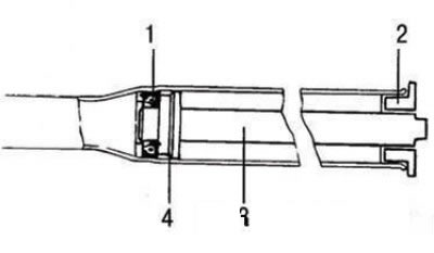
Steering gear for vehicles without power steering: 1 – steering draft; 2 - anther; 3 - dust cap; 4 – a tip of steering draft; 5 – a protective cover of steering draft; 6 – a case of the steering mechanism; 7 – a protective cover of steering draft
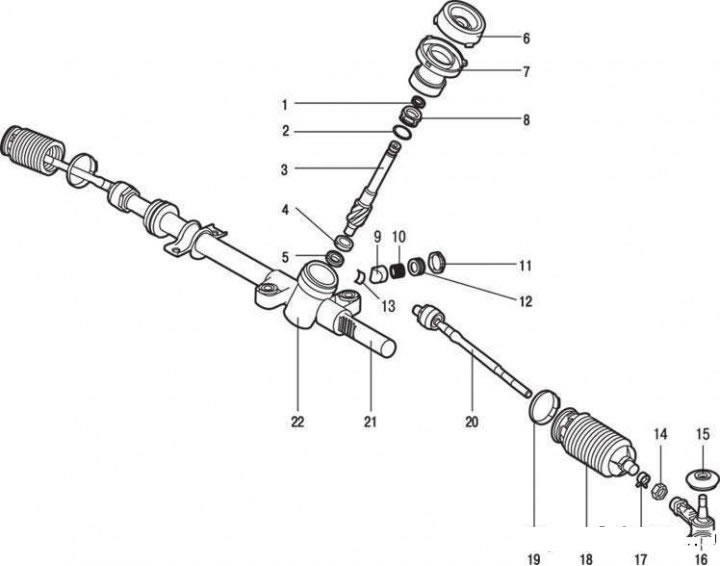
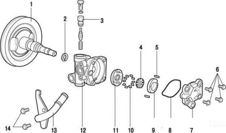
Steering gear assembly for cars without ST-21 booster: 1 - stuffing box; 2 - sealing ring; 3 - drive gear; 4 - bearing; 5 - stuffing box; 6 - anther; 7 - dust cap; 8 - top plug; 9 - rail stop; 10 - rail stop spring; 11 - locknut; 12 - adjusting screw of the rail stop; 13 - insert; 14 - nut; 15 - protective cover; 16 – a tip of steering draft; 17 - clamp; 18 - protective cover; 19 - collar; 20 – steering draft; 21 - rail; 22 - steering gear housing
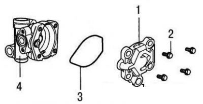
The steering gear of vehicles without power steering is shown in Figure 5.30, steering gear assembly (without amplifier).
Withdrawal
Place the car on a lift.
Raise the vehicle.
Disconnect the front muffler.
Remove the front wheels.
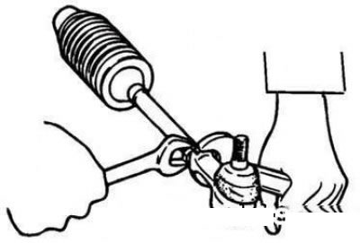
Knock out the locking cotter pin of the nut and press the ball joint pin of the tie rod end out of the steering knuckle with a puller.
In salon disconnect a steering shaft from the steering mechanism.
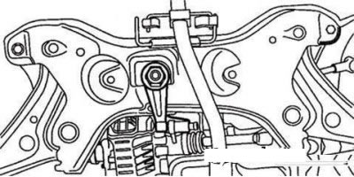
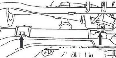
Gearbox Rear Mounting Bracket
Turn away bolts of fastening of a back bracket of a suspension bracket of a box before.
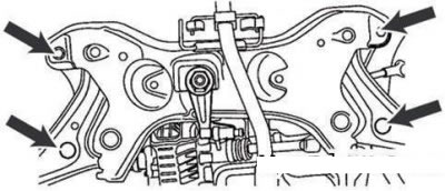
Subframe mounting bolts
Place a gearbox jack under the subframe and remove the four subframe mounting bolts.
Checking the technical condition and adjustment
Steering gear mounting bolts
Turn away a bolt of fastening of the steering mechanism and remove a collar of fastening.
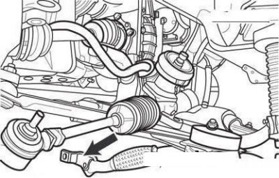
Removing the steering gear assembly with rods
Remove the steering link assembly by pulling it towards the right side of the vehicle.
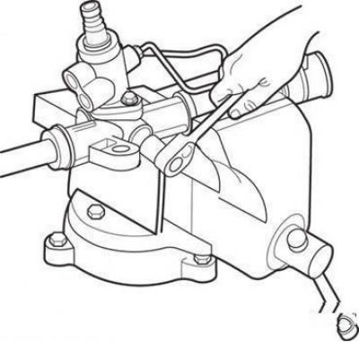
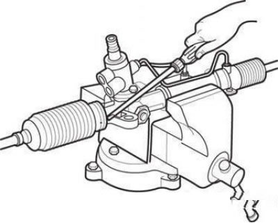
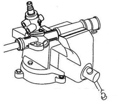
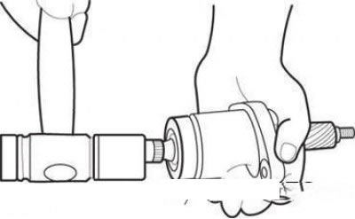
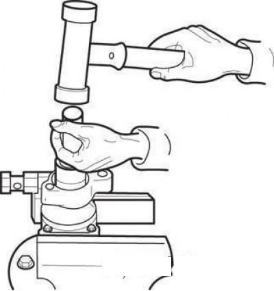
Clamp the steering mechanism in a vise with brass or aluminum lining.
Attention! It is allowed to clamp the steering mechanism in a vice only with its mounting part. Pinching any other part of it may cause damage to the steering gear.
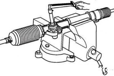
Checking the torque of the drive gear
Check the torque of the drive gear by rotating it at a speed of one revolution in about 4-6 seconds.
Torque 0.6–1.3 Nm.
Attention!
- The drive gear torque is measured over the entire travel of the rack.
- If the torque is not correct, adjust the rack stop, then check the torque again.
- If the correct torque cannot be obtained by adjusting the rack stop, check the rack stop parts and replace them if necessary.
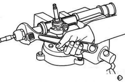
Turn the tie rod sharply several times.
Using a spring balance, measure the moment of resistance to turning the tie rod. It should be equal to 8–22 Nm.
If the received value exceeds norm, replace steering draft.
Attention! If the torque of resistance to rotation is below the specified limit, further use of the tie rod is possible, provided that its rotation occurs smoothly, without excessive play.
Check protective covers for damage and material degradation.
Make sure the covers are installed correctly.
Replace defective covers with new ones.
Disassembly
Removing the tie rod end
Remove the tie rod end.
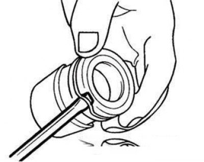
Clamp the tie rod end in a vise and remove the ball joint cover.
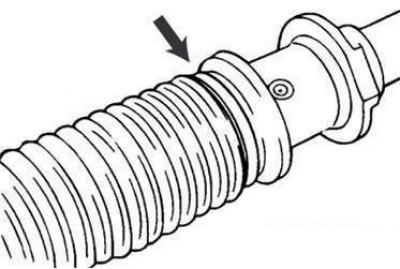
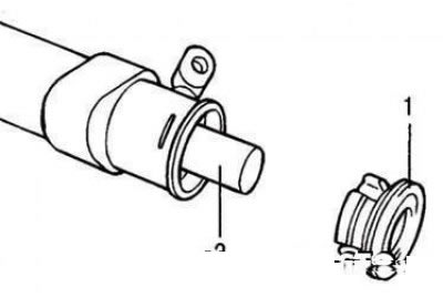
Collar of fastening of a protective cover of a lath
Remove the clamp securing the rail protective cover.
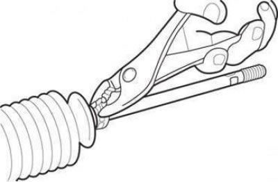
Removing the rail cover fastening clamp.
Remove the rail cover fastening clip.
Remove the rack cover by sliding it onto the tie rod.
Note. When installing the cover, check the rail for signs of corrosion.
Use a chisel to bend the lock washer that secures the tie rod to the rack.
Unscrewing the locknut of the adjusting screw of the rail stop.
Loosen the locknut of the rack stop adjusting screw.
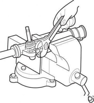
Unscrewing the adjusting screw of the rail stop.
Loosen the rail stop adjusting screw with a 14 mm socket wrench.
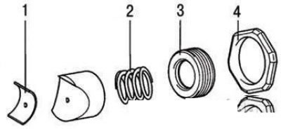
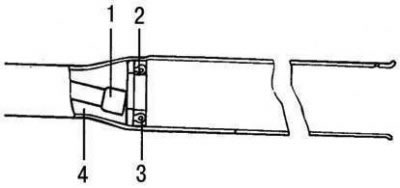
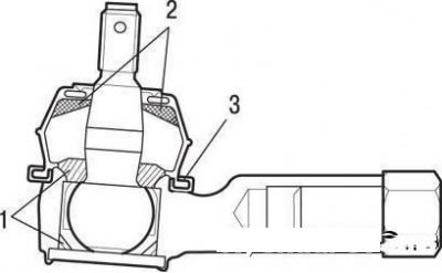
Rail stop: 1 - insert; 2 - stop spring; 3 - adjusting screw; 4 - locknut.
Unscrew the locknut, remove the stop spring, rack stop and insert.
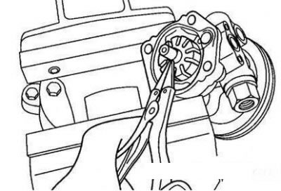
Unscrewing the inner ball joint of the steering rod.
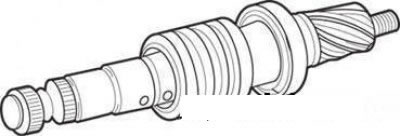
Move the rack all the way inside the steering gear housing and clamp the crankcase at the level of the toothed part of the rack in a vise with brass jaws. Turn away an internal spherical joint of steering draft and disconnect draft from a lath.
Remove the rack from the steering box.
Attention! Pull out the rack towards the left side of the car so as not to damage the insert with the teeth of the rack.
Assembly
Apply grease of the specified brand to the rack, insert the rack into the steering gear housing, install the drive gear into the housing.
Insert the rail into the crankcase from the left side.
When installing the drive gear, engage it with the rack.
Remove excess grease.
Before installing the steering gear oil seal, apply grease to it.
Note. Replace the seal with a new one.
Install the rack stop, stop spring, stop adjusting screw and tighten the lock nut.
Tighten the rail stop adjusting screw to 11 Nm, then unscrew it by an angle of 30–60°. Tighten the adjusting screw locknut.
Attention! Adjust the rail stop at the middle position of the rail. Install the locknut on the sealant.
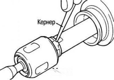
Locking the steering rod to the rack by punching
Attach the tie rod to the rack and lock it with a punch.
Reinstall the rail cover and secure it with the tie and clip.
Clamp the tie rod end in a vise and install the ball joint boot.
Establish a tip on steering draft.
Installation
Install the steering gear through the right side of the vehicle.
Attach the steering gear to the subframe.
Raise the subframe with a jack and secure it to the body.
Attach the rear transmission mount bracket. Attach the tie rod ends to the steering knuckles.
Install the front silencer.
Lower the car.
Install the front wheels.
In salon connect a steering shaft to the steering mechanism.
Vehicles with power steering
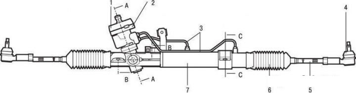
The steering gear of cars with power steering: 1 - anther; 2 - dust cap; 3 - pipelines of the hydraulic system; 4 – a tip of steering draft; 5 – steering draft; 6 – a protective cover of steering draft; 7 – a case of the steering mechanism
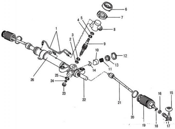
The steering gear of vehicles equipped with power steering, as an assembly: 1 - pipelines of the hydraulic system; 2, 5 - glands; 3, 4 - bearings; 6 - anther; 7 - dust cap; 8 - distributor housing; 9 - distributor; 10 - rail stop; 11 - rail stop spring; 12 - locknut; 13 - adjusting screw of the rail stop; 14 - insert; 15, 19 - protective covers; 16 - nut; 17 – a tip of steering draft; 18 - clamp; 20 - clamp; 21 – steering draft; 22 - rail; 23 - plug; 24 - nut; 25 - bearing; 26 - steering gear housing
Withdrawal
Place the car on a lift.
Drain the hydraulic fluid from the power steering system.
Remove the front wheels.
Knock out the locking cotter pin of the nut and, using the tool, press the ball joint of the tie rod end out of the steering knuckle.
In salon disconnect a steering shaft from the steering mechanism.
Raise the vehicle.
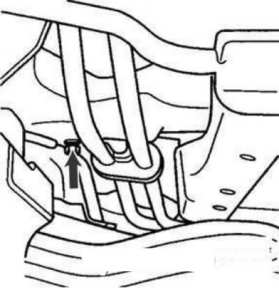
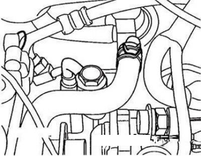
Remove the high pressure hose clamp and remove the power steering drain hose clamp bolt.
Disconnect the front muffler.
Turn away bolts of fastening of a back bracket of a suspension bracket of a transmission.
Turn away a bolt of fastening of the steering mechanism and remove a collar of fastening.
Place a gearbox jack under the subframe and remove the four subframe mounting bolts.
Disconnect from the steering mechanism the union of the pipeline of a high pressure and the drain pipeline.
Remove the steering link assembly by pulling it towards the right side of the vehicle.
Checking the technical condition and adjustment
Turn away a bolt of fastening of the steering mechanism and remove a collar of fastening.
Remove the steering link assembly by pulling it towards the right side of the vehicle.
Clamp the steering mechanism in a vise with brass or aluminum lining.
Attention! It is allowed to clamp the steering mechanism in a vice only with its mounting part. Pinching any other part of it may cause damage to the steering gear.
Check the torque of the drive gear by rotating it at a speed of one revolution in about 4-6 seconds; the torque should be 0.6–1.3 Nm.
Note. The drive gear torque is measured over the entire travel of the rack.
If the torque is not correct, adjust the rack stop, then check the torque again.
If the correct torque cannot be obtained by adjusting the rack stop, check the rack stop parts and replace them if necessary.
Turn the tie rod sharply several times.
Using a spring balance, measure the moment of resistance to turning the steering rod, it should be equal to 8–22 Nm.
Attention! If the torque of resistance to rotation is below the specified limit, further use of the tie rod is possible, provided that its rotation occurs smoothly, without excessive play.
If the received value exceeds norm, replace steering draft.
Check protective covers for damage and material deterioration.
Make sure the covers are installed correctly.
Replace defective covers with new ones.
Disassembly
Remove the tie rod end.
Clamp the tie rod end in a vise and remove the ball joint cover.
Collar of fastening of a protective cover of a lath
Remove the clamp securing the protective cover of the rail (figure 5.49).
Note. When installing the cover, check the rail for signs of corrosion.
Remove the rack cover by sliding it onto the tie rod.
Slowly extending the rack, drain the working fluid from the steering gear housing.
Use a chisel to bend the lock washer that secures the tie rod to the rack.
Disconnect the tie rod from the rack.
Attention! When disconnecting the tie rod from the rack, make sure that the rack is not subjected to twisting force.
Loosen the locknut of the rack stop adjusting screw.
Loosen the stop with a socket wrench «at 14».
Unscrew the locknut, remove the rack stop adjusting screw, stop spring, rack stop and insert from the steering mechanism.
Disconnect the supply line from the steering gear housing.
Bolts of fastening of the case of the distributor
Remove the distributor housing by unscrewing the bolts.
When the end of the retaining ring comes out of the slotted hole, turn the rack stopper counterclockwise and remove the retaining ring.
Attention! Be careful not to damage the rail.
Remove the rack bushing and rack from the steering box.
O-ring crankcase
Remove the O-ring from the crankcase.
Remove the oil seal from the rack bushing.
Knocking out the distributor from the housing
Knock the distributor out of the distributor housing with a soft-faced hammer.
Remove the oil seal and ball bearing from the distributor housing.
Take out an epiploon and a sealing ring from a case of the steering mechanism.
Attention! Take care not to damage the drive gear valve cylinder mirror in the steering gear housing.
Removing the stuffing box and ball bearing from the distributor housing: 1 - tool 09573-21200; 2 - thrust washer; 3 - stuffing box; 4 - fixture 09573-21000
Using a special tool, remove the oil seal and ball bearing from the distributor housing (figure 5.54).
Checking the technical condition
1. Rake.
- Check rack teeth for damage and wear.
- Check the seal contact surface for damage.
- Check the rail for bent or twisting.
- Check the packing ring for damage or wear.
- Check the seal for damage or wear.
2. Drive gear and distributor.
Drive gear and distributor
- Check drive gear teeth for damage or wear.
- Check the seal contact surface for damage.
- Check the packing ring for damage or wear.
- Check the seal for damage or wear.
3. Bearing.
- Check the bearing for seizing or excessive running noise.
- Check that there is no excessive clearance in the bearing.
- Make sure all bearing needles are present.
- Check the steering gear cylinder mirror for damage and the protective covers for damage, cracks or aging.
Assembly
Lubricate the entire surface of the rail oil seal with PSF-3 working fluid.
Installing the oil seal in the crankcase of the steering mechanism: 1 - fixture 09573-21200; 2 - fixture 09573-21000; 3 - fixture 09555-21000; 4 - fixture 09573-21100
Install the oil seal in the steering box in the position shown in the figure.
Apply PSF-3 fluid to the entire surface of the rack gland bushing.
Install the oil seal in the rack bushing.
Apply working fluid to the entire surface of the O-ring and install the O-ring into the rack bushing.
Lubricate rack teeth with SAE J310a, NLGI #2 EP multipurpose grease.
Note. Be careful not to clog the rail vent hole with grease.
Installing the rack bushing: 1 - rack bushing; 2 - rail
Insert the rack into the steering gear case, insert the rack bushing and slide it inward until it aligns with the crankcase groove, then fix the bushing.
Using the special tool, install the oil seal and ball bearing into the distributor housing.
Install the distributor in the steering gear housing, for which apply working fluid and grease to the distributor.
Apply working fluid to the oil seal, install it in the steering gear housing and fix the distributor and O-ring in the crankcase.
Attach the tie rod and lock it by punching with a chisel.
Install the insert, rack stop, stop spring in the order shown in the figure. Before installing, apply sealant to the threads of the rail stop adjusting screw.
With the rack in the middle position, turn the rack stop adjusting screw into the steering gear housing and with a socket wrench «at 14» tighten it with a torque of 12 Nm, then unscrew the screw at an angle of 30–60°and tighten the screw locknut with a torque of 50–70 Nm.
Tighten the system feed pipe fitting to the specified torque and install the rubber pad on the adhesive.
Apply silicone grease to the place where the protective cover is installed (into a groove) steering traction.
Install a new clamp on the case.
Note. Replace the clamp with a new one every time you install the boot.
Replace the cover without twisting it.
Laying grease in the protective cover of the ball joint of the steering rod: 1 - grease A; 2 - grease B; 3 - sealant
Place grease in the protective boot of the tie rod ball joint and on the lip of the boot, and secure the boot with the circlip by inserting it into the groove of the joint.
Grease A - POLE LUB GLY 801K or equivalent.
Grease B SHOWA SUNLIGHT MB 2 or equivalent.
The cavity and edge of the protective cover are THREE BOND.
Install the ball joint to the tie rod.
Check drive gear torque.
Installation
Install the steering gear in place across the right side of the vehicle.
Attach the steering gear to the subframe.
Connect the high pressure line and drain line to the steering gear.
Raise the subframe with a jack and secure it to the body.
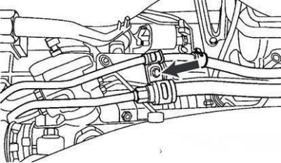
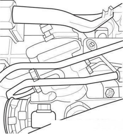
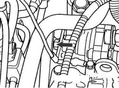
Clamp for high pressure hose and drain pipe (indicated by an arrow)
Secure the high pressure hose and drain pipe with a clamp.
Install the rear transmission mount bracket.
Attach the front muffler.
Lower the vehicle slowly.
Attach the tie rods to the steering knuckles.
Install wheels.
Attach the steering shaft to the steering mechanism.
Pour working fluid into the hydraulic booster reservoir.
Remove air from the hydraulic booster system.
Hoses and pipelines of the hydraulic booster
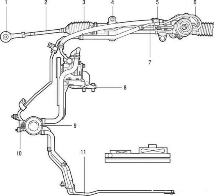
Hoses and pipelines of the hydraulic booster: 1 – a tip of steering draft; 2 – steering draft; 3 - rack cover; 4 – a collar of fastening of the steering mechanism; 5 – a collar of fastening of a hose of a high pressure; 6 - pipeline and high pressure hose; 7 - drain pipeline; 8 – an arm of fastening of the pump of the hydraulic booster; 9 – a reservoir of the hydraulic booster pump; 10 - tank mounting bracket; 11 - oil cooler
Withdrawal
Place the car on a lift.
Drain the hydraulic fluid from the power steering system.
Remove the front wheels.
Knock out the locking cotter pin of the nut and press the ball joint pin of the tie rod end out of the steering knuckle with a puller.
In salon disconnect a steering shaft from the steering mechanism.
Raise the vehicle.
Remove the high pressure hose clamp and remove the power steering drain hose clamp bolt.
Disconnect the front muffler.
Remove the bolts securing the rear gearbox mount to the subframe.
Place a gearbox jack under the subframe and remove the four subframe mounting bolts.
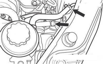
High pressure pipe fitting and drain pipe fitting
Disconnect from the steering mechanism the union of the pipeline of a high pressure and the drain pipeline.

Power steering pump high pressure hose fitting
Lower the vehicle and disconnect the high pressure hose fitting from the power steering pump (in case of removal of the high pressure hose).

Power steering pump high pressure hose
Disconnect the high pressure hose and remove it (in case of removal of the high pressure hose).
Remove the windshield washer reservoir and two clamps securing the drain pipe and hose (when removing the drain pipe).
Remove the drain pipe clamp, drain pipe and hose (when removing the drain pipe and hose).
Loosen the two screws on the top of the front bumper (when removing the drain pipe).
Drain pipe clamp bolt
Remove the bolt (10 mm) drain pipe fastening clamp (when removing the drain pipe).
Disconnect from the hose on the reservoir side of the power steering pump and remove the drain pipe (when performing work on the drain pipeline).
Installation
Place the car on a lift.
Insert the drain pipe from the top of the front bumper to the bottom of the bumper and tighten the two mounting bolts.
Install the drain pipe and hose, tighten the clamp bolt and install the tank (when installing the drain pipe and hose).
Drain pipe clamps
Connect the drain pipe to the hose from the side of the hydraulic booster tank and from the side of the drain pipe and hose, fix it with clamps (when installing a drain pipe).
Reinstall the high pressure hose and pipe, connect them to the power steering pump (when installing a high pressure hose and pipe).
Raise the vehicle.
Connect the high pressure pipe and drain pipe to the steering gear.
Place a gearbox jack under the subframe and install and tighten the four subframe mounting bolts.
Tighten the high pressure pipe and drain pipe clamp bolt.
Attach the rear transmission mount bracket to the subframe
Attach the front muffler to the engine.
Lower the car.
In salon connect a steering shaft to the steering mechanism.
Tighten the two mounting bolts at the top of the front bumper (when installing the pipeline).
Attach the tie rod ends to the steering knuckles.
Install the front wheels.
Pour working fluid into the power steering pump reservoir.
Checking the technical condition
Check the hoses for cracks by twisting them by hand.
Make sure the hoses do not touch other parts.
Filling the hydraulic booster system with working fluid
Pour fluid into the power steering pump reservoir up to the mark «MAX».
Raise the front of the car with a jack until the wheels are hanging and turn the steering wheel from lock to lock five to six times at a speed of 13 min-1, activating the power steering pump, turning the engine over with the starter, but not starting it.
Start the engine at idle and turn the steering wheel from lock to lock in both directions several times until there are no air bubbles in the fluid in the reservoir.
Filling is complete if the liquid is not milky and its level is constantly at the mark «MAX».
Attention! If the fluid level changes when the steering wheel is turned, or fluid overflows from the reservoir when the engine is stopped, then the air from the system has not been completely removed. It is necessary to repeat the bleeding of the system, as indicated above, since the presence of air leads to increased noise during the operation of the hydraulic booster and its premature failure.
Power steering pump
Power steering pump: 1 – pump shaft with drive pulley; 2 - ring; 3 - fitting details; 4 - rotor; 5 - locking pin; 6 - fastening bolts; 7 - cover; 8 - gasket; 9 - cam ring; 10 - blades; 11 - cover; 12 - pump casing; 13 - suction pipe; 14 - bolts for fastening the suction pipe
The power steering pump is shown in the figure. It provides pressure and circulation of the working fluid in the system. On Hyundai Getz cars, a power steering vane pump is installed. Vane pumps are most widely used in the hydraulic steering systems of passenger cars due to their high efficiency and low sensitivity to wear of working surfaces. The pump is mounted on the engine, it is driven by a belt drive from the crankshaft.
Withdrawal
Disconnect the high pressure hose from the pump.
suction hose
Disconnect the suction hose from the suction pipe and drain the liquid into a prepared container.
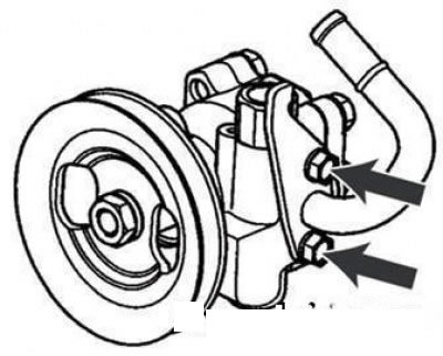
Bolt of a tension of a belt of a drive of the pump of the hydraulic booster
Loosen the power steering pump drive belt tension adjusting bolt.
Remove the drive belt from the power steering pump pulley.
Remove the power steering pump by unscrewing the pump mounting bolts and the drive belt tension adjustment bolt.
Remove the power steering pump bracket.
Disassembly
Suction pipe fixing bolts
Unscrew the two mounting bolts and remove the suction pipe and the sealing ring from the pump housing.
Power steering pump: 1 - pump cover; 2 – bolts of fastening of a cover; 3 - gasket; 4 - pump housing
Remove the pump cover by unscrewing the four bolts.
Remove the cam ring.
Use pliers to remove the circlip from the rotor shaft.
Remove the rotor and blades.
Remove the side cover of the pump.
Remove the shaft with the pulley from the pump housing.
Remove the stuffing box from the pump housing.
Unscrew the fitting from the pump housing and remove the control valve and valve spring from the fitting.
Remove the o-ring from the fitting.
Attention! Do not disassemble the control valve.
Checking the technical condition
Check the free length of the control valve spring.
It should be 36.5 mm.
Make sure the control valve is not bent.
Check the rotor shaft for wear and damage.
Check the drive belt for wear and material degradation.
Check the grooves of the rotor and blades for stratified abrasive wear.
Check the contact surfaces between the cam ring and the vanes for stratified abrasion.
Assembly
Install the o-ring, control valve spring, and control valve into the fitting. Screw the fitting into the pump body.
Pressing the stuffing box into the pump housing
Using tool 09222-32100, press the stuffing box into the pump housing.
Install the rotor shaft with pulley into the pump housing.
Check the rotor blades for damage.
Install the side cover and rotor.
Insert the locking pin into the groove of the pump casing and install the cam ring.
Install the rotor.
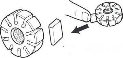
Installing the blades in the rotor
Install the blades into the rotor with the rounded edges facing out.
Mounting the rotor on the shaft
Secure the rotor to the shaft with a circlip using pliers.
Install gasket and pump cover.
Install the suction pipe with O-ring.
Installation
Install the pump on the mounting bracket, put the drive belt on the pulley and tighten the belt tension adjustment bolt to 2.5–3.0 N·m for vehicles with engines with a working volume of 1.3 l, to 3.5–5.0 N·m for vehicles with engines with a displacement of 1.5 liters.
Connect the suction hose.
Attention! Connect the high pressure hose to the pump with the color coded end.
Connect the high pressure hose to the pump.
Restore the PSF-3 fluid level in the power steering reservoir to normal.
Note. When connecting the high pressure hose to the pump, make sure it is not twisted or touching other parts.
Remove air from the hydraulic booster system.
Check the power steering pump discharge pressure.
Electric Power Steering
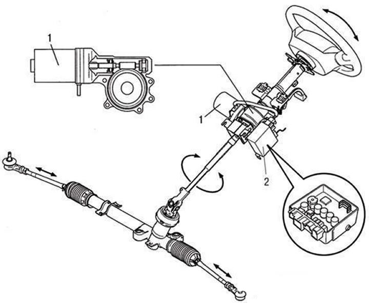
Electric Power Steering: 1 – the electric motor of the amplifier of a steering; 2 - electronic control unit
The principle of operation of the electric power steering
Additional force on the steering wheel is generated by the power steering electric motor, the action of which does not depend on the operating mode of the vehicle engine. The control of the electric motor is carried out depending on the driving conditions, which provides a higher adaptability of the degree of boost than with the use of the hydraulic booster, and reduces energy consumption. The electric booster allows you to reduce environmental pollution, since it does not use liquid, and the absence of pipelines and hydraulic hoses in the engine compartment allows you to reduce the weight of the car.
The steering wheel torque sensor, which is part of the electric power steering system, converts the change in the magnetic field into a current signal depending on the difference in the angle of rotation between the input and output shafts when the torsion bar is twisted.
Electric power steering (EURU) located inside the cabin and therefore protected from pollution, exposure to high temperatures (from the engine in the engine compartment) and the negative impact of the environment.
Attention!
- Do not strike electronic components. If dropped or struck, replace with new ones.
- Protect electronic components from high temperatures and humidity.
- Do not touch the wire leads to prevent them from being deformed and to prevent the possibility of exposure to static electricity.
- Do not strike parts of the electric motor and steering wheel torque sensor. If dropped or struck, replace with new ones.
- Separate and connect contact sockets at the switched off ignition.
Troubleshooting Guide
Symptom | Element to test | Explanations | Recommendations |
| Increased motor noise | electric motor | Explicit or implicit damage. At use of damaged (when falling) parts, the vehicle can pull to the side. precision parts The electric motor and ECU are sensitive to vibration and shock. Sudden damage may be caused by overload | Do not use EURA subjected to blow. Avoid Overloading Nodes amplifier |
| Malfunction of electrical circuits (soldering defects, printed circuit board damage, precision parts damage) | Electronic control unit | Same | Do not use EURA subjected to blow |
| Insufficient turning force | Steering torque sensor wheels | Overloading the input shaft can cause steering wheel torque sensor malfunction | Do not hit the connecting parts (during installation and tightening). Remove the steering wheel with special device (don't hit him). Do not use impacted parts |
| Insufficient turning force (unequal effort when turning left and right) | Shaft | | Do not use EURA that has been hit |
| Power steering not working | Wiring | Disconnection between connectors and wires | Check wiring |
| Deviation of the turning force from the norm Due to a malfunction of the electric motor or EURU | Electric motor and EURU | Under normal conditions, the amplifier is waterproof. The ingress of even a small amount of moisture can cause malfunction of precision parts | Maintain normal temperature and humidity during storage. Not let the car get into the water |
Troubleshooting Electric Power Steering
The electric power steering ECU stores and displays faults that occur (tab. 5.1). Before troubleshooting the EURU, check the power supply to the amplifier.
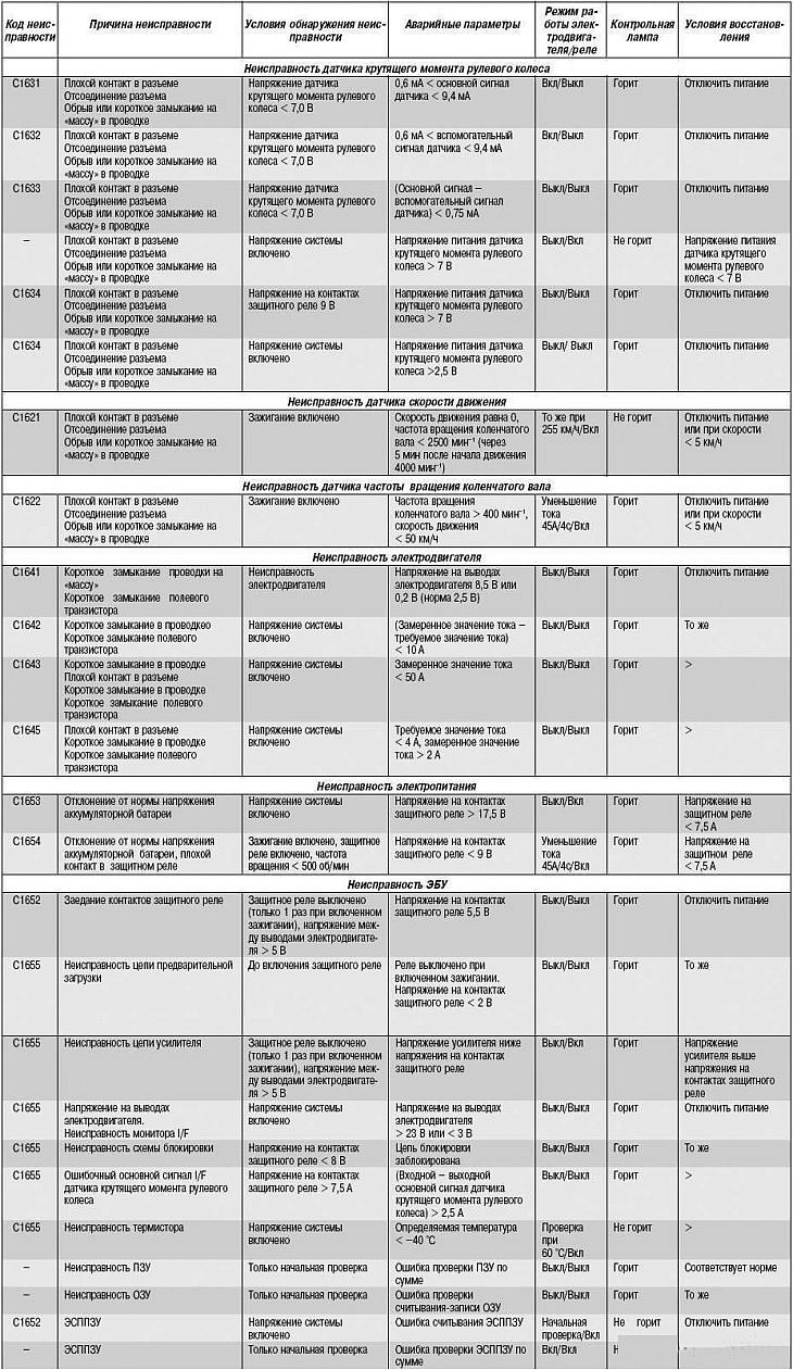
Fault codes (when using the HI-SCAN device)
Code | Fault |
| C1631 | Open or short in steering wheel torque sensor main signal circuit |
| C1632 | Open or short in steering wheel torque sensor auxiliary signal circuit |
| C1633 | Mismatch between the main and auxiliary steering wheel torque sensor signal |
| C1634 | Steering Wheel Torque Sensor Power Circuit Malfunction |
| C1621 | Speed Sensor Signal Circuit Malfunction |
| C1622 | Crankshaft Speed Sensor Signal Circuit Malfunction |
| C1641 | Short circuit on «mass» in the motor circuit |
| C1642 | Increased motor supply current |
| C1643 | Excessively high motor supply current |
| C1645 | Insufficient motor supply current |
| C1652 | ECU EURU (protection relay sticking) |
| C1655 | ECU EURU (preload chain) |
| C1653 | Overvoltage in the system |
| C1654 | Undervoltage in the system |
With a working system, the EURU control lamp lights up when the ignition is turned on and goes out after the engine is started. If a malfunction occurs, the EURU control lamp continues to burn even after the engine is started, but if the malfunction has already occurred before the engine is started, then the lamp will not burn.
The EURU control lamp lights up under the following conditions:
- the vehicle speed is not more than 1 km/h, the crankshaft speed is not less than 2500 min-1 for more than 20 s;
- crankshaft speed not more than 400 min-1, speed not less than 50 km/h for more than 21 s.
Emergency operating modes of the electric power steering