


Cars without electric power steering
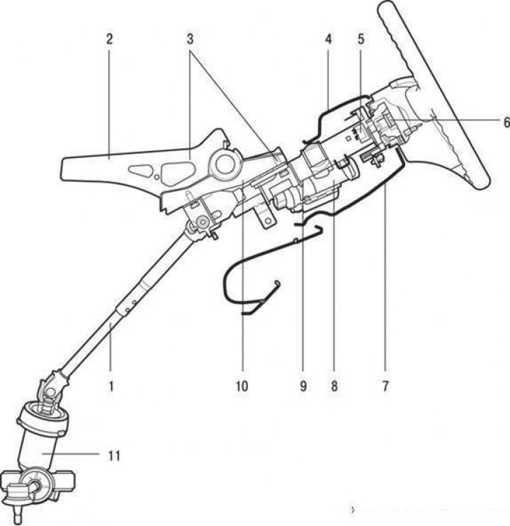
Steering column and steering shaft without steering wheel position adjustment mechanism: 1 – lower shaft; 2 – instrument panel beam; 3 – steering shaft bracket mounting bolts; 4 – Upper steering column trim cover; 5 – steering column switch block; 6 – steering wheel mounting nut; 7 – lower steering column trim cover; 8 – anti-theft device; 9 – lower instrument panel trim; 10 – steering shaft; 11 – steering mechanism
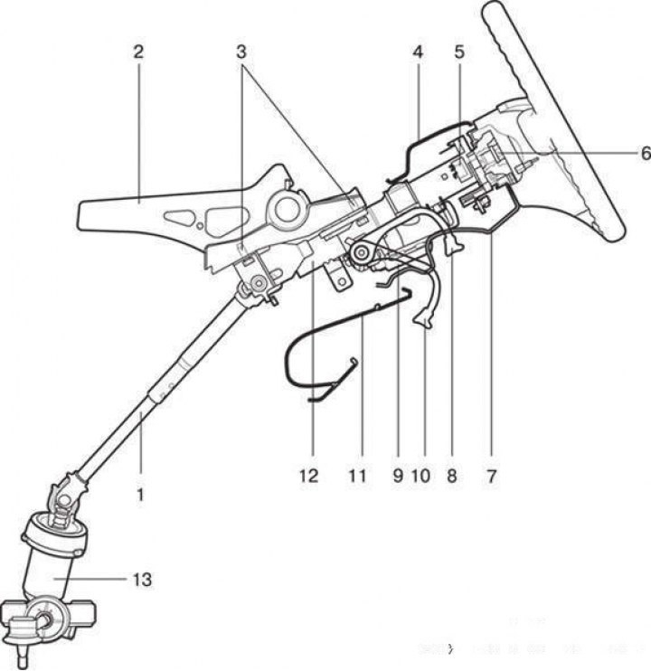
Steering column and steering shaft with steering wheel position adjustment mechanism: 1 – lower shaft; 2 – instrument panel beam; 3 – steering shaft bracket mounting bolts; 4 – Upper steering column trim cover; 5 – steering column switch block; 6 – steering wheel mounting nut; 7 – lower steering column trim cover; 8 – locking position of the latch; 9 – steering wheel position lock handle; 10 – lock release position; 11 – lower instrument panel trim; 12 – steering shaft; 13 – steering mechanism
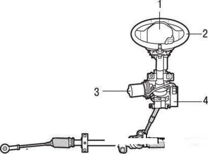
Steering column and steering shaft of vehicles with electric power steering (rear view): 1 – Horn switch trim (driver airbag module); 2 – steering wheel; 3 – electric motor; 4 – electronic control unit
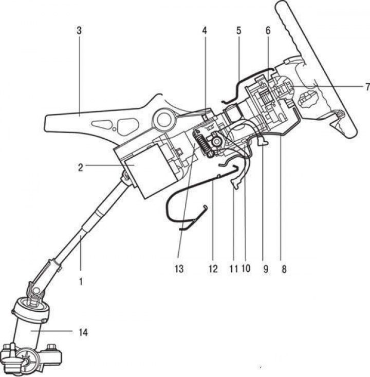
Steering column and steering shaft of vehicles with electric power steering (side view): 1 – lower shaft; 2 – electronic control unit; 3 – instrument panel beam; 4 – steering shaft bracket mounting bolts; 5 – Upper steering column trim cover; 6 – steering column switch block; 7 – steering wheel mounting nut; 8 – lower steering column trim cover; 9 – locking position of the latch; 10 – steering wheel position lock handle; 11 – lock release position; 12 – lower instrument panel trim; 13 – steering shaft; 14 – steering mechanism
Removal
Disconnect the negative ("–") cable from the battery.
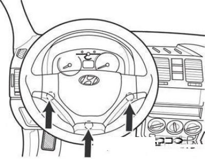
Driver Airbag Module Mounting Bolts
Remove the driver's airbag module by unscrewing the mounting bolts shown by the arrows in the figure.
Note: On vehicles without an airbag, remove the horn switch cover.
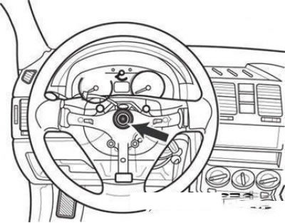
Steering wheel mounting nut
Loosen the steering wheel mounting nut.
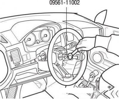
Removing the steering wheel from the shaft using a puller
Align the marks on the steering shaft and the steering wheel. Remove the steering wheel from the shaft using a puller.
Note: Do not remove the steering wheel by hammering as this may damage the steering shaft.
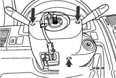
Steering column trim cover mounting screws
Remove the steering column trim cover by unscrewing the three screws shown by the arrows in the figure.
Disconnect the airbag module contact disc and steering column switch assembly connectors.
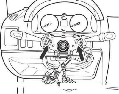
Removing the steering column switch unit
Remove the steering column switch assembly by pressing on it in the places shown by the arrows in the figure.
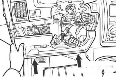
removing the lower trim of the instrument panel
Remove the lower instrument panel trim by unscrewing the two mounting bolts.
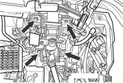
Steering shaft bracket mounting bolts
Remove the four steering shaft bracket mounting bolts.
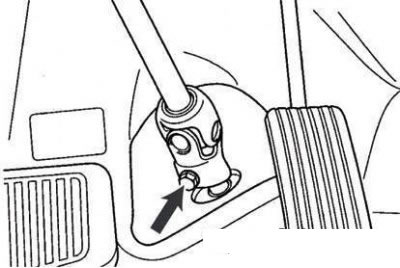
Bolt securing cardan joint to steering gear drive pinion
Loosen the bolt securing the universal joint to the steering gear drive pinion.
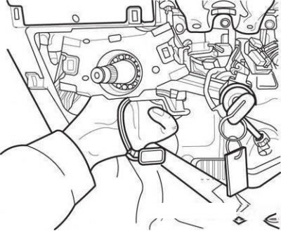
Removing the steering shaft assembly
Remove the steering shaft assembly.
Checking the technical condition
Check the steering shaft for damage and deformation.
Check the shaft connections for gaps, damage and smooth movement.
Check the ball bearing for wear or damage.
Disassembly and assembly
If it is necessary to remove the anti-theft device, use a chisel to make a groove for the screwdriver slot on the heads of the special mounting bolts.
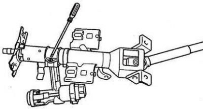
Loosen the bolts securing the anti-theft device
Use a screwdriver to unscrew the two special mounting bolts.
Remove the anti-theft device from the steering shaft.
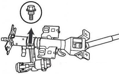
Special bolt for fastening the anti-theft device to the steering shaft
When installing the anti-theft device, tighten new special bolts to secure the device to the steering shaft.
Tighten the special bolts with a wrench until the heads shear off.
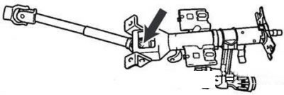
Lower shaft to steering column assembly mounting bolts
Remove the mounting bolts (12 mm) of the lower shaft to the steering column assembly and the upper shaft.
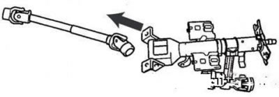
Disconnecting the lower shaft from the steering column assembly
Disconnect the lower shaft from the steering column assembly and the upper steering shaft.
Assemble in the reverse order of disassembly.
Cars with electric power steering
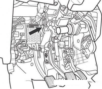
Electric Power Steering Connector
Disconnect the electric power steering connector.
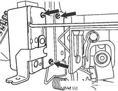
Electric Power Steering Mounting Screws
Remove the power steering unit by unscrewing the three mounting screws.
Assemble in the reverse order of disassembly.
Installation
Install the steering shaft in place and tighten the four mounting bolts.
Screw in the bolt securing the cardan shaft joint to the steering gear drive pinion, located behind the brake pedal.
Tighten the four "hard-tightened" steering shaft mounting bolts.
Install the lower instrument panel trim and screw in the two mounting bolts.
Install the steering column switch assembly onto the steering column until it snaps into place.
Install the air bag module contact disc and connect the steering column switch assembly connector.
Install the upper and lower steering column covers and tighten the mounting screws.
Install the steering wheel and tighten the mounting nut.
Install the airbag module and tighten the three mounting bolts.
Connect the negative ("–") cable to the battery.